Contents
Index
List of Figures
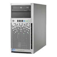
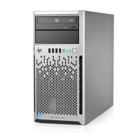
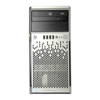
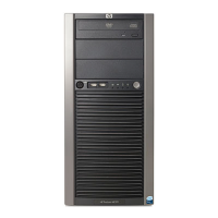
Figure 1-1: ProLiant ML310 server ......................................................................................1-3
Figure 1-2: Drive bay configuration......................................................................................1-4
Figure 1-3: Front panel components......................................................................................1-5
Figure 1-4: Rear panel connectors.........................................................................................1-6
Figure 1-5: NIC connector ....................................................................................................1-7
Figure 1-6: SCSI system board components.........................................................................1-8
Figure 1-7: ATA system board components .......................................................................1-10
Figure 2-1: ProLiant ML310 server installed into a rack......................................................2-3
Figure 2-2: Powering up the server.......................................................................................2-8
Figure 2-3: Inserting a CD into the CD-ROM drive ...........................................................2-11
Figure 3-1: Removing the front bezel ...................................................................................3-3
Figure 3-2: Removing the access panel.................................................................................3-4
Figure 3-3: Removing a bezel blank .....................................................................................3-5
Figure 3-4: Removing a drive tray ........................................................................................3-6
Figure 3-5: Disconnecting the hard drive cables (SCSI model)............................................3-8
Figure 3-6: Disconnecting the hard drive cables (ATA model)............................................3-9
Figure 3-7: Removing a hard drive .....................................................................................3-10
Figure 3-8: Removing the drive compartment ....................................................................3-11
Figure 3-9: Locating the hard drive screws.........................................................................3-12
Figure 3-10: Installing a 3.5-inch hard drive.......................................................................3-13
Figure 3-11: Installing a hard drive into a removable media bay drive tray .......................3-14
Figure 3-12: Installing a hard drive into a removable media bay........................................3-15
Figure 3-13: Removing a device from the removable media bay .......................................3-16
Figure 3-14: Removing the rails from the drive tray...........................................................3-18
Figure 3-15: Installing a tape drive .....................................................................................3-19
Figure 3-16: Removing the bezel from the drive cage........................................................3-20
Figure 3-17: Removing media bay blanks...........................................................................3-21
Figure 3-18: Removing the CD-ROM drive .......................................................................3-21
Figure 3-19: Moving the CD-ROM drive ...........................................................................3-22
Figure 3-20: Attaching the rails to the drive cage...............................................................3-23
Figure 3-21: Expansion slots...............................................................................................3-24
Figure 3-22: Removing the expansion slot cover................................................................3-25
Figure 3-23: Releasing the expansion board retainer..........................................................3-26
Figure 3-24: Installing an expansion board.........................................................................3-26
viii HP ProLiant ML310 Server Setup and Installation Guide
HP CONFIDENTIAL
Writer: Ted Weiman File Name: a-frnt.doc
Codename: Son of Beast Part Number: 274431-002 Last Saved On: 11/22/02 1:55 PM