125
Table 202 Set the jumpers on the FIC-4BSE
Jumper settings & description
Interface 0
S2
• To use a 100-ohm matched resistance for data transmission, place
the jumper over pins 1 and 2.
• To do otherwise, place the jumper over jump pins 2 and 3.
• See Figure 139.
S1
• To use a 100-ohm matched resistance for data receiving, place the
jumper over jump pins 1 and 2.
• To do otherwise, place the jumper over jump pins 2 and 3.
• See Figure 139.
Interface 1
S4
• To use a 100-ohm matched resistance for data transmission, place
the jumper over pins 1 and 2.
• To do otherwise, place the jumper over jump pins 2 and 3.
• See Figure 139.
S3
• To use a 100-ohm matched resistance for data receiving, place the
jumper over jump pins 1 and 2.
• To do otherwise, place the jumper over jump pins 2 and 3.
• See Figure 139.
Interface 2
S6
• To use a 100-ohm matched resistance for data transmission, place
the jumper over pins 1 and 2.
• To do otherwise, place the jumper over jump pins 2 and 3.
• See Figure 139.
S5
• To use a 100-ohm matched resistance for data receiving, place the
jumper over jump pins 1 and 2.
• To do otherwise, place the jumper over jump pins 2 and 3.
• See Figure 139.
Interface 3
S8
• To use a 100-ohm matched resistance for data transmission, place
the jumper over pins 1 and 2.
• To do otherwise, place the jumper over jump pins 2 and 3.
• See Figure 139.
S7
• To use a 100-ohm matched resistance for data receiving, place the
jumper over jump pins 1 and 2.
• To do otherwise, place the jumper over jump pins 2 and 3.
• See Figure 139.
Interface LEDs
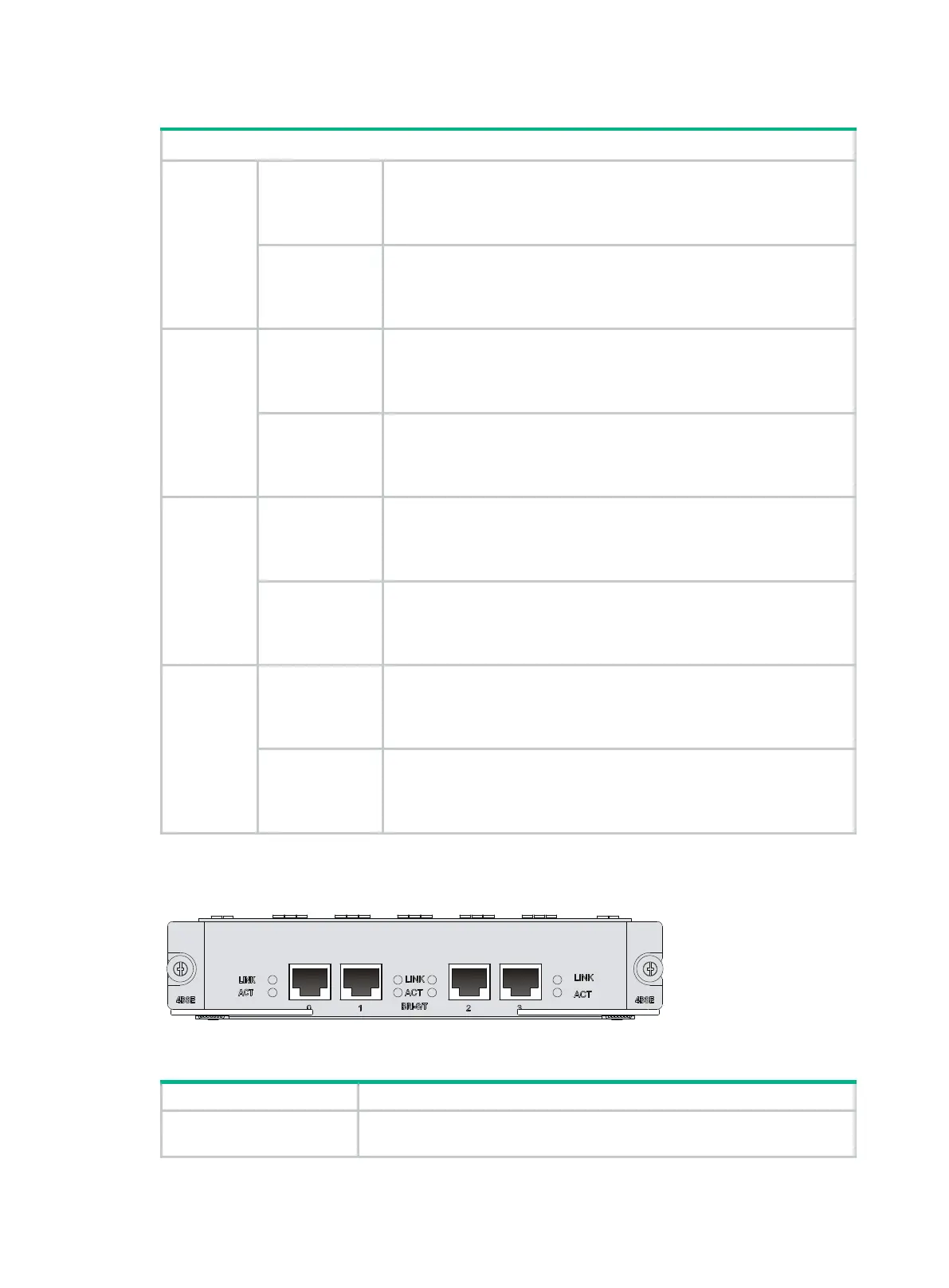
Figure 148 FIC-4BSE panel
Table 203 LED description
LINK
• Off means no link is present.
• On means a link is present.

 Loading...


