166
Figure 174 Connecting the U interface cable to the SIC-1BS interface module
2. If the service provider provides an ISDN S/T interface cable, directly connect the cable to the
RJ45 interface of the SIC-1BS interface module.
Figure 175 Connecting the S/T interface cable to the SIC-1BS interface module
E&M interface
E&M interface appearance and the applicable model
MIM-4E&M/FIC-4E&M modules support Bell I, II, III, V switches, and 2-wire & 4-wire voice signals.
As a best practice, use Bell V 4-wire voice signal to communicate with the router.
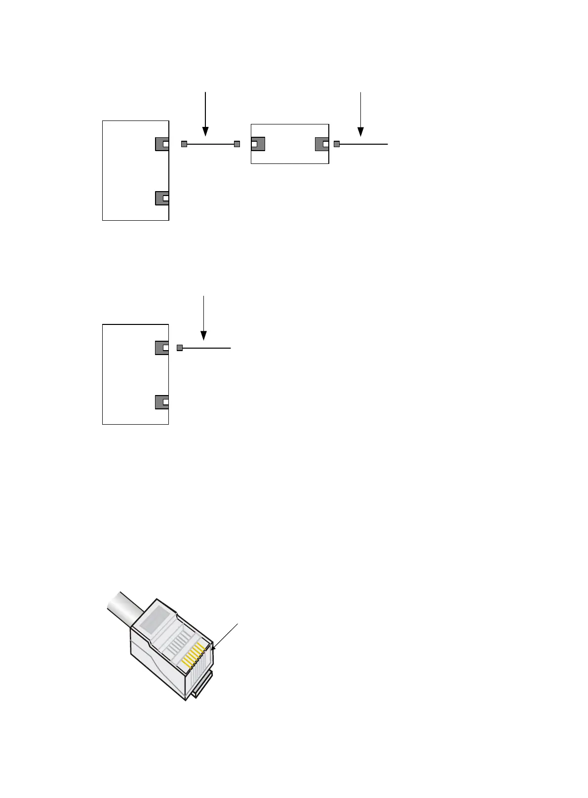
The sequence of E&M RJ-45 pins is shown in the following figure, numbered 1 to 8 in order from
PIN1:
Figure 176 Sequence of RJ-45 pins
Magnetic-core telephone cable
SIC-1BS
……
ISDN U interface cable of Service provider
NT1
S/T U
SIC-1BS
……
ISDN S/T interface cable of Service provider

 Loading...


