171
G.SHDSL interface
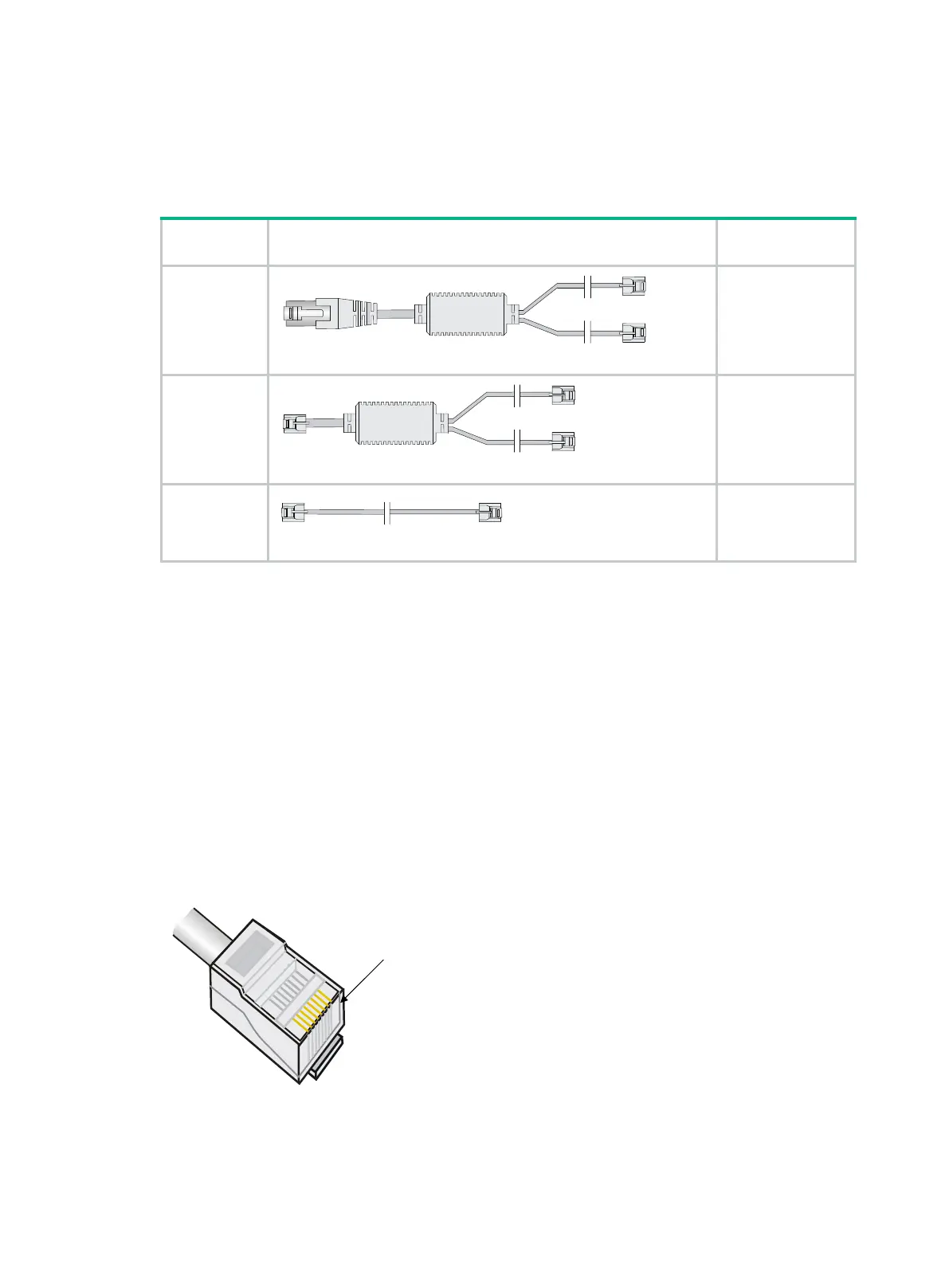
Appearance and applicable models of the G.SHDSL interface adapter cable
Table 248 Appearance and applicable models of the G.SHDSL interface adapter cable
Cable Appearance
Applicable
8-wire
G.SHDSL
interface
cable
1 × RJ45 (8 wires) < ---- > 2 × RJ11 (4 wire)
DSIC-1SHDSL-8W
4-wire Y type
G.SHDSL
interface
cable
1 × RJ11 (4 wire) < ---- > 2 × RJ11 (2 wire)
MIM-1SHL-4W
4-wire I type
G.SHDSL
interface
cable
1 × RJ11 (4 wire) < ---- > 1No RJ11 (4 wire)
MIM-1SHL-4W
Connecting a DSIC-1SHDSL-8W interface module cable
1. Connect the RJ45 connector on one end of the 8-wire G.SHDSL interface cable to the RJ45
interface on the DSIC-1SHDSL-8W interface module
2. The other end of the cable provides two RJ11 connectors. They can be connected to two 4-core
telephone cable.
Use correct wire pairs when the DSIC-1SHDSL-8W interface module cable is operating in different
modes:
• When the interface module cable is operating in dual-wire mode, use Line 0.
• When the interface module cable is operating in four-wire mode, use Line 0 and Line 1.
• When the interface module cable is operating in six-wire mode, use Line 0, Line 1, and Line 2.
The sequence of the RJ-45 connector pins is shown in Figure 174, numbered 1 to 8 in order from
PIN1.
Figure 182 Sequence of RJ-45 pins

 Loading...


