167
Table 245 Pinouts of E&M interface cable (Bell V 4-wire)
RJ-45 Pin Signal Signal direction
1 — —
2 E IN
3 RING0 IN
4 RING1 OUT
5 TIP1 OUT
6 TIP0 IN
7 M OUT
8 SG Ground
he 4E&M modules cannot determine the interface types (Bell I/II/III/V), cable types (2-wire or
-wire), and pinouts (E/M/Tx/Rx) of the peer switch. You must prepare the interface cables of the
4E&M modules according to the on
-
site conditions. To ensure the EMC of the router, install a ferrite
core near the connector of the E&M module interface cable at the router side.
Connecting the cable
1. Connect one end of the magnetic-core telephone cable to the RJ11 or RJ45 interface of the
interface module.
2. Connect the other end of the magnetic-core telephone cable to the remote device interface.
24FXS interface
24FXS interface cable appearance and the applicable model
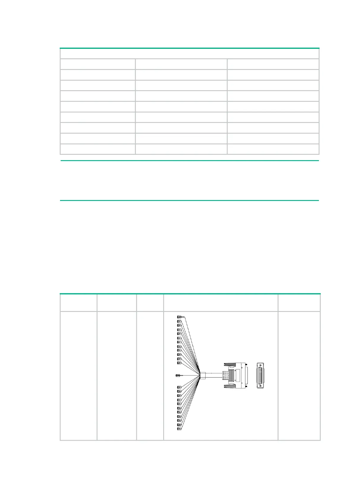
Table 246 24FXS interface cable appearance and the applicable model
Product
Description Cable Appearance
Applicable
JG318A
HPE A-MSR
50 pin D-sub
Male to 24 ×
RJ-11 Plug
15m Router
Cable
24FXS
interface
cable
24 × RJ11 < ---- > 1 × D50
FIC-24FXS

 Loading...


