144
Connecting an Ethernet cable
1. Connect one end of an Ethernet cable to an Ethernet interface on the module and the other end
to the Ethernet interface on the peer device. Because the Ethernet interface of the module
supports MDI/MDIX auto-sensing, you can use a straight-through cable or crossover cable to
connect the interface.
2. Check the status of the LED of the Ethernet interface after power-on. For the status of the LED,
see the relevant part in this manual.
Fiber port
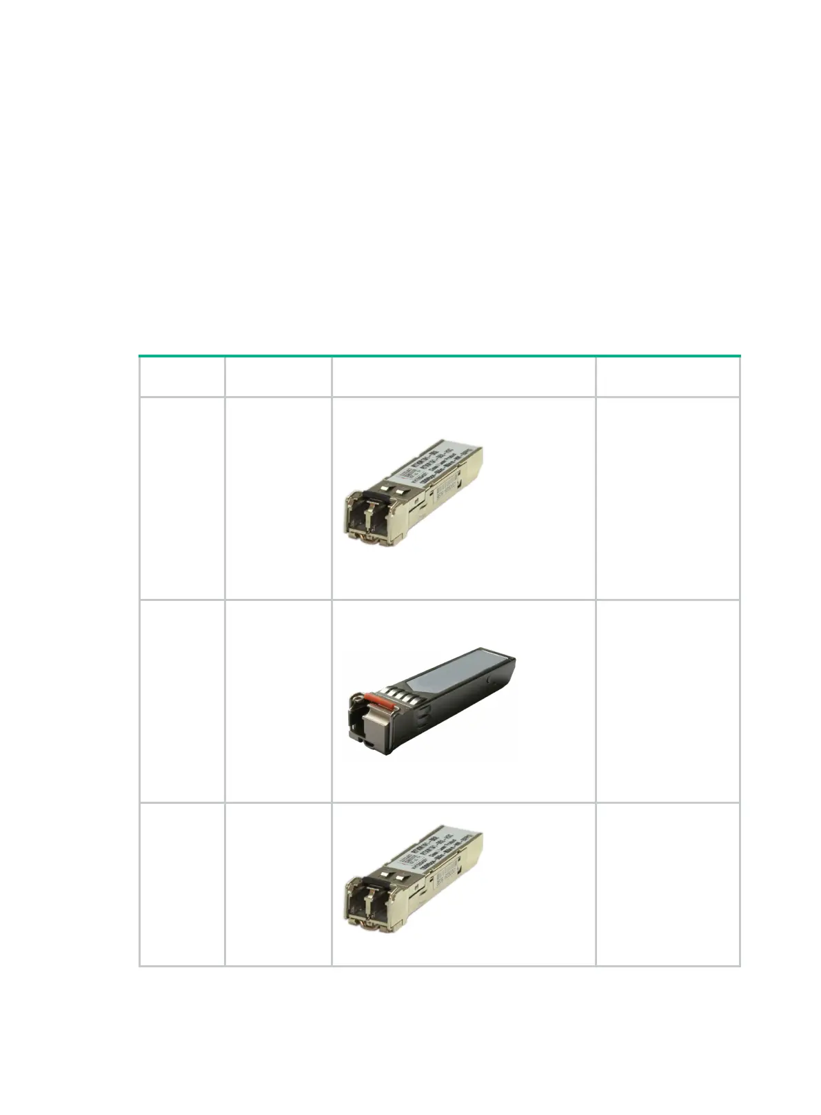
Appearances and applicable models of transceiver modules and optical fibers
Optical interfaces must work with SFP transceiver modules and optical fibers with LC connectors.
Table 232 Ethernet cable appearance and applicable models
Product
Cable Appearance Applicable models
JD090A
JD091A
JD102B
JD120B
SFP transceiver
module
SIC-1FEF
MIM-1POS
FIC-1POS
FIC-1CPOS
HMIM-1POS
HMIM-1CPOS
MIM-1ATM-OC3
FIC-1ATM-OC3
HMIM-8GSWF
SIC-4GSWF
JD100A
JD101A
100-Mbps BIDI
transceiver
module
SIC-1FEF
MIM-1POS
FIC-1POS
FIC-1CPOS
HMIM-1POS
HMIM-1CPOS
MIM-1ATM-OC3
FIC-1ATM-OC3
HMIM-8GSWF
SIC-4GSWF
JD118B
JD119B
JD061A
JD062A
JD063B
JD103A
JD098B
JD099B
SFP transceiver
module
SIC-1GEC
FIC-1GEF
FIC-2GEF
HMIM-8GSWF
SIC-4GSWF

 Loading...


