HT2000H_en_n.doc Page 165 of 167
13 Appendix C – Connection panel
13.1 GC connector
The GC connector is on the connection panel (see paragraph 2.1.4 “Connection panel“).
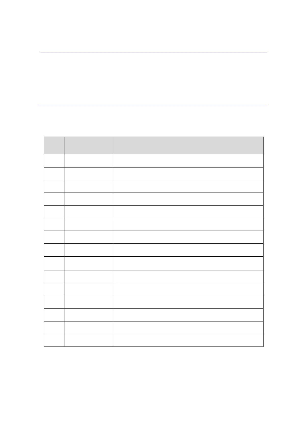
pin #
Function
Note
1 +5 Volts
Exit = Max. 20 mA
2 FREE3-IN
Signal input (true low); Low-level = 0÷0.5 V Hi-level = 4÷12 V
3 SAMPINS-NO
Exit = Relay contact (open by default)
4 GCRDY
Signal input (true high); Low-Level = 0÷0.5 V Hi-level = 4÷12 V
5 GND
Ground
6 SAMPINSCOM
Relay common contact
7 FREE1-NC
Exit = Relay contact (closed by default)
8 ENDSAMP-NC
Exit = Relay contact (closed by default)
9 GCRDY
Signal input (true low); Low-Level = 0÷0.5 V Hi-level = 4÷12 V
10 FREE1-NO
Exit = Relay contact (open by default)
11 ENDSAMPL-NO
Exit = Relay contact (open by default)
12 FREE2
Signal input (true low); Low-Level = 0÷0.5 V Hi-level = 4÷12 V
13 FREE1-COM
Relay common contact
14 ENDSAMPL-COM
Relay common contact
15 SAMPINS-NC
Exit = Relay contact (closed by default)
Relay specification: V
max
= 24 V ; I
max
= 1A DB15 Connector