HT2000H_en_n.doc Page 21 of 167
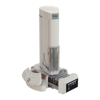
1 MOVING TRAY (1 rack with 42 sample positions)
2 TURRET: holds the syringe
3 TOUCH SCREEN DISPLAY
4 INCUBATION OVEN/SHAKER: where samples are heated.
The incubation oven/shaker may also be located on the left or right side of the autosampler,
depending on how the autosampler is configured. Left/Right side configuration is factory set.
5 INJECTION AREA: region where an injection can be made.
The injection area may also be located on the left or right side of the autosampler.
6 SYSTEM INTEGRITY TOOL AREA: only if the System integrity kit option has been
supplied (see paragraph 1.7.2 “Options”.)
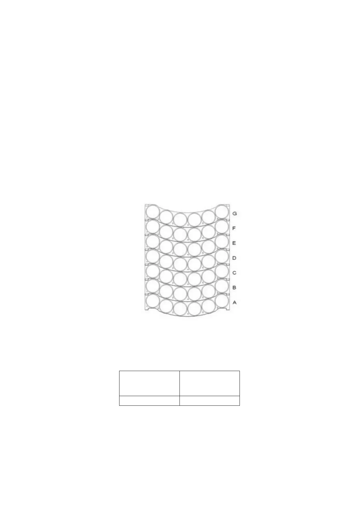
2.1.1.2 HT2000H/HT2000HT Sample rack
HT2000H/HT2000HT standard version uses a 42-position rack.
Figure 3: HT2000H/HT2000HT 42 position rack
Each vial is identified with two digits (a letter and a number):
A. 6
Letter (row) Number (column)
The letters (from A to G) indicate the rows, while the numbers indicate the columns (from 1 to 6).