HT2000H_en_n.doc Page 31 of 167
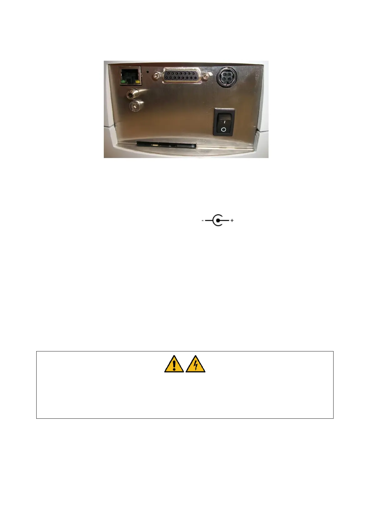
Figure 22: Connection panel
1 I/O: ON/OFF Power switch
2 Power cable socket: low voltage power connection (external power
supply)
3 RS232C connector: for remote control (serial connection, optional, not
present in this picture)
4 RJ45 10/100 auto-sensing connector: for remote control (Ethernet connection, standard)
5 GC connector: for other devices (GC, analyzer....)
6 Service Ethernet reset: reserved for Service Representative
7 Service Emergency release: reserved for Service Representative
8 Gas connection for syringe purge: inlet 1/8”
For further information on this purge line connection please refer to paragraph 3.3.4 “Purge line
connections”.
Warning
Use only the power supply system supplied with the autosampler. The use of different system
could cause damage to the equipment and/or compromise safety.
The autosampler is powered by an external power supply, as shown in the figure below: