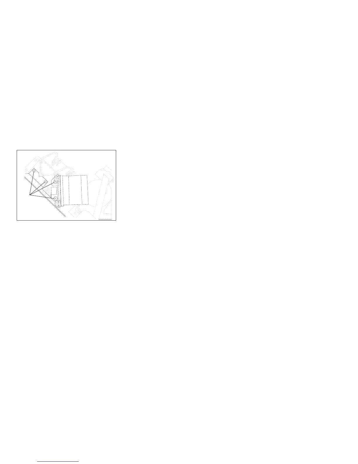
5. Remove the 4 carriage motor support bracket screws. Separate the motor bracket from the fan bracket. The
motor can now be moved to access the right side mounting screw in Step 9 on page 454.
Attention: Do not damage the cables.
6. Remove the carriage assembly. See “Carriage Assembly” on page 437.
7. Remove the manual sheet feed tray. See “Manual Sheet Feed Tray” on page 425.
8. Remove the manual sheet feed paper presence sensor screw (behind the foam). Note the location of the
cable to aid installation. To prevent damage to the sensor cable, move the sensor cable outside of the left
printer frame.
Screws
Figure 189. Carriage Motor Support Bracket Screws.
(Viewed From Right Side)
Chapter 5. Removals and Adjustments 453