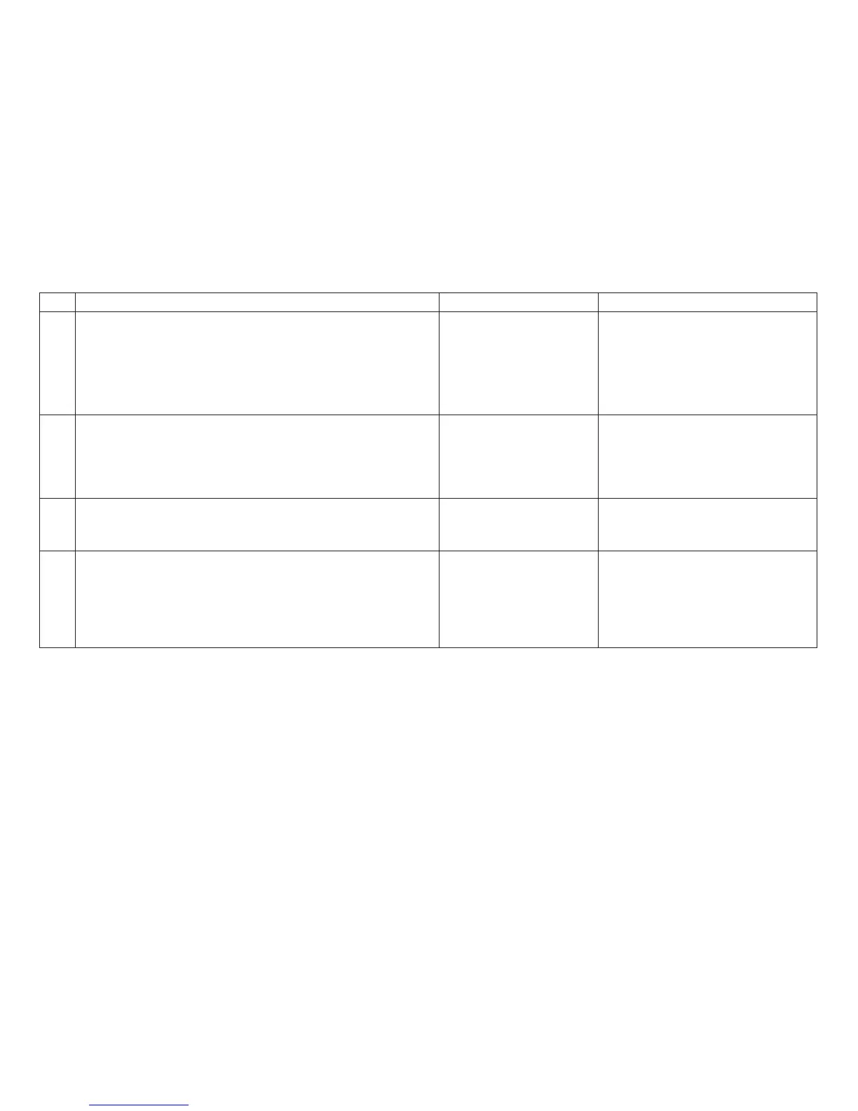
Table 6. MAP 0121: Attachment, Models 001, 002, or 003 (continued)
Step Questions/Actions Yes No
14.
Models 001, 002:
Follow “Attachment Card Procedure 2” on page 56, and
return here.
Do the logic board microcode modules match the host
connect feature?
Go to step 15. Repair as needed. Run T&D in
Automatic Mode to verify correct
printer operation. See “How To Run
the Test and Diagnostic (T&D)
Programs” on page 201.
15.
Models 001, 002:
Are both U54 and U2 modules correctly oriented?
Go to step 16. Repair as needed. Run T&D in
Automatic Mode to verify correct
printer operation. See “How To Run
the Test and Diagnostic (T&D)
Programs” on page 201.
16.
Are you here due to a ’028’ display message? The
problem can be intermittent or solid. The printer can be
Ready, but will not print.
Go to step 17. Go to step 18 on page 49.
17.
Install a coax attenuator (P/N 80F9513) on the connector on
the back of the printer between the printer and the coax
cable.
Is the problem corrected?
Run T&D in Automatic
Mode to verify correct
printer operation. See
“How To Run the Test
and Diagnostic (T&D)
Programs” on page 201.
Go to step 18 on page 49.
Chapter 1. Diagnosing Problems
48