MOl
860
Tape Write Diagnostic
This
MOl
tests
all
the tape write functions of the internal and
the
5106
Auxiliary Tape units. It also analyzes
all
failures
except erase
as
shown
in
the following chart.
Be
sure
to
record the tape status on
at
least
the
first failure. Refer
to
the
tape status byte information
in
this section.
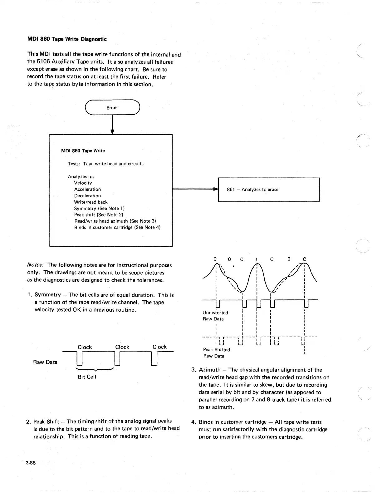
Enter
MDI
860
Tape Write
Tests: Tape write head and circuits
Analyzes
to:
Velocity
Acceleration
Deceleration
Write/read back
Symmetry (See Note 1 )
Peak shift (See Note
2)
Read/write head azimuth (See Note 3)
Binds in customer cartridge (See Note 4)
Notes: The following notes are for instructional purposes
only. The drawings are
not
meant
to
be
scope pictures
as
the diagnostics are designed
to
check the tolerances.
1. Symmetry - The bit cells are of equal duration. This
is
a function of the tape read/write channel. The tape
velocity tested
OK
in
a previous routine.
Raw Data
Clock
--.--
Bit
Cell
Clock Clock
2. Peak Shift - The timing shift of the analog signal peaks
is
due
to
the bit pattern and
to
the tape
to
read/write head
relationship. This
is
a function of reading tape.
3-88
861 - Analyzes
t~.
erase
c
o c
c
o
c
,
Undistorted
I :
I I
Raw Data I I
':
:
1 I I I
I I I I :
----1-,
r---,
I----J
,..--1.,
r-----'
r---
I I I
LJ
tJ
; t J
LJ
I
LJ
I
Peak Shifted 1
Raw Data
I
3. Azimuth - The physical angular alignment of the
read/write head gap with the recorded transitions on
the tape. It
is
similar
to
skew, but due
to
recording
data serial
by
bit and by character
(as
apposed
to
parallel recording on 7 and 9 track tape) it
is
referred
to
as
azimuth.
4. Binds
in
customer cartridge -
All
tape write tests
must run satisfactorily with
the
diagnostic cartridge
prior
to
inserting the customers cartridge.
,I'"
'\..
/