c
f
(
(
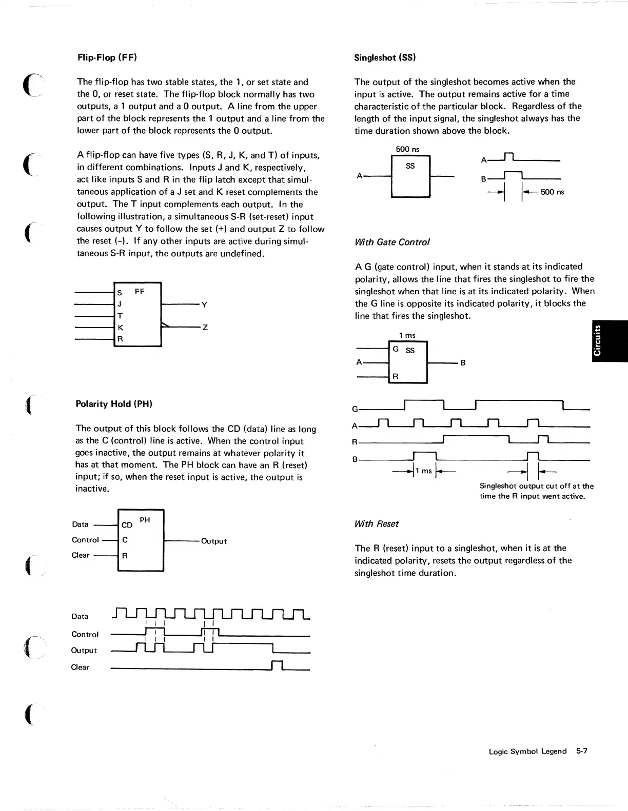
Flip-Flop (FF)
The flip-flop has two stable states,
the
1,
or
set state and
the 0, or reset state. The flip·flop block normally has two
outputs, a 1
output
and a 0
output.
A line from
the
upper
part
of
the block represents the 1
output
and a line from the
lower part
of
the
block represents the 0
output.
A flip·flop can have five types
(S,
R,
J,
K,
and T)
of
inputs,
in
different combinations. Inputs J and
K,
respectively,
act like inputs
Sand
R
in
the
flip latch except
that
simul-
taneous application
of
a J set and K reset complements
the
output.
The T input complements each
output.
In
the
following illustration, a simultaneous S·R (set·reset) input
causes
output
Y
to
follow the set (+) and
output
Z
to
follow
the reset (-).
If
any other inputs are active during simul-
taneous S-R input,
the
outputs
are undefined.
S
FF
J
y
T
K
z
R
Polarity Hold (PH)
The
output
of
this block follows the
CD
(data) line
as
long
as
the
C (control) line
is
active. When
the
control input
goes inactive, the
output
remains
at
whatever polarity it
has
at
that
moment. The
PH
block can have an R (reset)
input;
if
so, when the reset input
is
active, the
output
is
inactive.
Data
CD
PH
Control
C
Output
Clear
R
Data
Control
Output
Clear
----------------~~
8ingleshot (88)
The
output
of the singleshot becomes active when
the
input
is
active. The
output
remains active for a time
characteristic
of
the
particular block. Regardless
of
the
length of
the
input signal,
the
singleshot always has the
time duration shown above the block.
500
ns
With Gate Control
A G (gate control) input, when it stands
at
its indicated
polarity, allows the line
that
fires
the
singleshot
to
fire
the
singleshot when
that
line
is
at
its indicated polarity. When
the G line
is
opposite its indicated polarity, it blocks the
line
that
fires
the
singleshot.
1 ms
G-----'
A
R---------~
L-..I1
__
_
B
_____
~r__l~------------~r1~------
~1msf_
-1
~
With Reset
Singleshot
output
cut
off
at
the
time
the
R
input
went
active.
The R (reset) input
to
a singleshot, when it
is
at
the
indicated polarity, resets
the
output
regardless
of
the
singleshot time du.ration.
Logic Symbol Legend 5-7