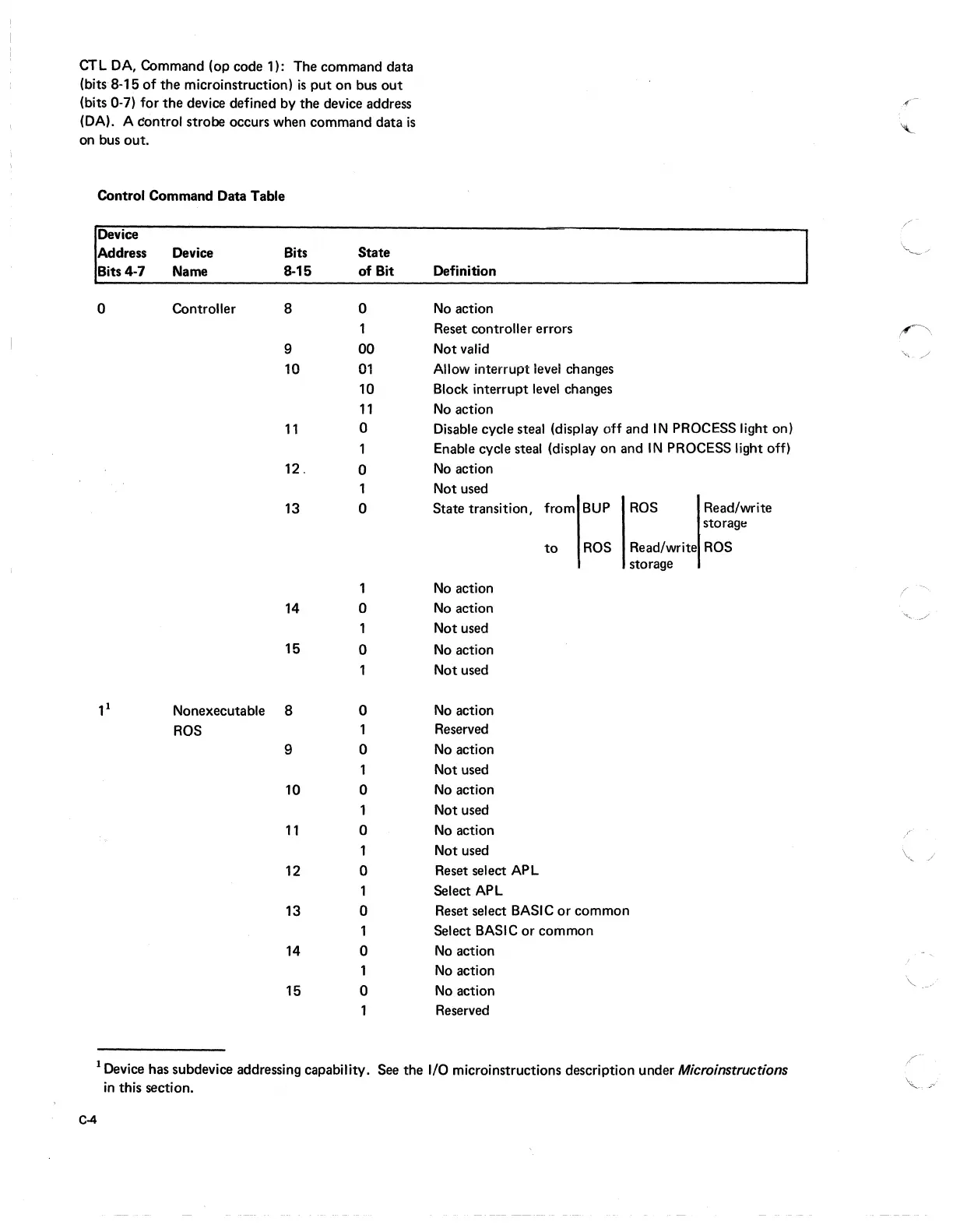
CTL DA, Command (op code 1): The command data
(bits
8-15
of
the
microinstruction)
is
put
on
bus
out
(bits 0-7) for
the
device defined by the device address
(DA). A dontrol strobe occurs when command data
is
on bus
out.
Control Command Data Table
Device
Address Device Bits
State
Bits 4-7
Name
8-15
of
Bit
Definition
0
Controller
8
0
No
action
Reset controller errors
9 00
Not valid
10
01
Allow interrupt level changes
10
Block interrupt
level
changes
11
No
action
11
0
Disable cycle steal (display off and
IN
PROCESS light on)
1
Enable cycle steal (display on and
IN
PROCESS light off)
12.
0
No
action
1 Not used
13
0
State transition,
from
BUP
ROS
Read/write
storagt:
to
ROS
Read/write
ROS
storage
1
No
action
14
0
No
action
1
Not used
15
0
No
action
Not used
11
Nonexecutable 8 0
No
action
ROS
1
Reserved
9
0
No
action
1
Not used
10
0
No
action
Not used
11
0
No
action
1
Not used
12
0
Reset select APL
1
Select APL
13
0
Reset select BASIC
or
common
1
Select BASIC
or
common
14
0
No
action
1
No
action
15 0
No
action
Reserved
1 Device has subdevice addressing capability. See the I/O microinstructions description under
Microinstructions
in
this section.
C-4
.r
"-
/~
~--/
~
~"i._
.,,/
I
'~"
"
..
~,/
\,
/
'"
,,-,'