(
(
(/
(
Oscillators/Clocks: The processor uses a 15.1 MHz
oscillator
to
generate 66.2 nanosecond clock pulses.
These multiclock cycle (MCC) pulses
are
used
to
control
data throughout the computing system. MCC pulses
make up the I phase (instruction) and the E phase
(execute) machine cycles.
Machine
Cycles
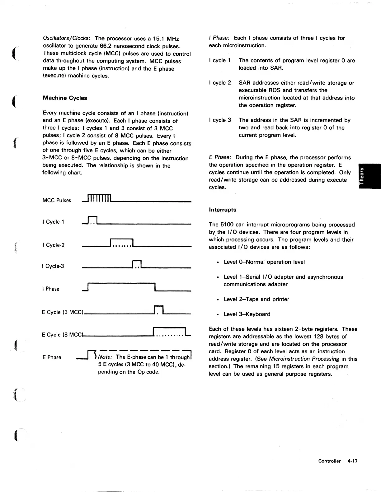
Every machine cycle consists
of
an
I phase (instruction)
and
an
E phase (execute).
Each
I phase consists
of
three I cycles: I cycles 1 and 3 consist
of
3 MCC
pulses; I cycle 2 consist
of
8 MCC pulses. Every I
phase is followed by
an
E phase.
Each
E phase consists
of
one through five E cycles, which can
be
either
3-
MCC or
8-
MCC pulses, depending on the instruction
being executed. The relationship is shown in the
following chart.
MCC
Pulses
..J
II II
I
IIIL..--
____
_
I Cycle-l
~--------------------------
I Cycle-2
___
...-III
•••••••
IL-
_______
_
I Cycle-3
________
~r.J~
______
__
I
Phase
J
E Cycle (3
MCC)
_______
.....I[l
...
____ _
E Cycle (8
MCC)
_______
----.I
..........
L
E
Phase
Jl
,;;e~T;;E-Pha:-c~b;;-
~ughl
5 E cycles (3
MCC
to
40 MCC),
de-
pending on the
Op
code.
I Phase:
Each
I phase consists
of
three I cycles
for
each microinstruction.
I cycle 1 The contents
of
program level register 0 are
loaded into SAR.
I cycle 2 SAR addresses either
read/write
storage
or
executable
ROS
and transfers the
microinstruction located at that address into
the operation register.
I cycle 3 The address
in
the SAR is incremented by
two
and read back into register 0
of
the
current program level.
E
Phase: During the E phase, the processor performs
the operation specified
in
the operation register. E
cycles continue until the operation is completed. Only
read/write
storage can be addressed during execute
cycles .
Interrupts
The 5100 can interrupt microprograms being processed
by.
the
I/O
devices. There are four program levels in
which processing occurs. The program levels and their
associated
I/O
devices are
as
follows:
• Level O-Normal operation level
•
Levell-Serial
I/O
adapter and asynchronous
communications adapter
• Level
2-
Tape and printer
•
Level
3-Keyboard
Each
of
these levels has sixteen
2-byte
registers. These
registers are addressable
as
the lowest 128 bytes
of
read/write
storage and are located on the processor
card. Register 0
of
each level acts
as
an
instruction
address register. (See
Microinstruction Processing. in this
section.) The remaining 15 registers in each program
level
can
be used
as
general purpose registers.
Controller 4-17