A suffix
is
added
to
a logic block function
to
clarify logic
usage. The suffix symbol
is
always placed
to
the
right of
the block function symbol and
is
separated by a blank or a
dash. The following suffixes are used with amplifier blocks:
AR-LT
AR-LD
AR-ID
AR-CD
AR-HD
AR-MD
AR-V
AR-DF
Magnet
Driver
Transmission line terminator
Transmission line driver
Indicator driver
Core driver
Magnetic head driver
Magnet driver (relay, clutch, solenoid, etc)
Voltage amplifier/analog voltage signal
Differential amplifier.
Differential
Amplifier
Odd
Count
(ODD)
The
output
of
odd
count
is
active only when
an
odd number
(such
as
1,
3,
5, and
7)
of
inputs are active. A G (gate
control) input might
be
present
in
the
common section
of
an
ODD block (refer
to
Functional Logic Blocks with Common
Inputs).
When the G line
is
at
the
indicated polarity, it gates
the input lines into
the
ODD logic block and the
output
line
is
determined by
the
odd function
of
the
block.
When
the
G line
is
opposite the indicated polarity,
the
output
line
is
also opposite its indicated polarity.
A
ODD
B
c
o
......
I I I I
A
iH
B
I I I
I
I I I
I
c
I I I I
I
I I I I
0
:
u-H
I I I
I I
E
rn.n
5-6
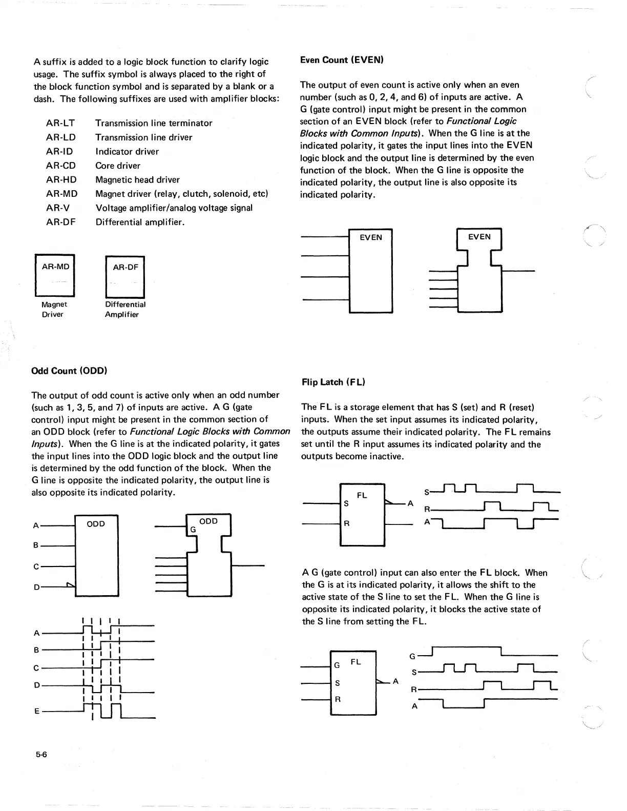
Even
Count
(EVEN)
The
output
of even
count
is
active only when an even
number (such as
0,2,4,
and 6)
of
inputs are active. A
G (gate control)
input
might be present in
the
common
section
of
an EVEN block (refer
to
Functional Logic
Blocks with Common Inputs).
When
the
G line
is
at
the
indicated polarity, it gates the input lines into
the
EVEN
logic block and
the
output
line
is
determined by
the
even
function
of
the block. When the G line
is
opposite the
indicated polarity,
the
output
line
is
also opposite its
indicated polarity.
EVEN
Flip Latch (FL)
The
FL
is
a storage element
that
has S (set) and R (reset)
inputs. When
the
set input assumes its indicated polarity,
the
outputs
assume their indicated polarity. The FL remains
set until the R input assumes its indicated polarity and
the
outputs
become inactive.
FL
5
----15
A
R----
....
----IR
A
A G (gate control) input can also enter the FL block. When
the G
is
at
its indicated polarity, it allows the shift
to
the
active state
of
the S line
to
set
the
F
L.
When
the
G line
is
opposite its indicated polarity, it blocks
the
active state
of
the S line from setting
the
FL.
G.-.J
G
FL
5
5
~A
R
n
r-L
R
A--'
(
~.