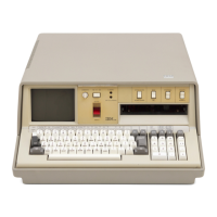
5100
Operations
POWER
ON
PROCEDURE, INITIALIZATION,
AND
BRING-UP DIAGNOSTIC
When
the 5100 is powered up
or
when the RESTART
switch is pressed, executable
ROS
provides the
controller
with
the instructions
of
the bring up
diagnostic. Before the user enters any programs
or
data, the controller executes these instructions
to
determine
if
the 5100 is operating correctly.
If
a failure
is detected during the bring up diagnostic, the 5100 will
stop
with
a bring up halt
or
a process check.
If
LOADO
or
CLEAR
WS
appears on the bottom line
of
the
display, the bring up routine and the IPL have run
successfully.
Upon completion
of
the bring up diagnostic, the
controller starts to execute the initial program load (lPL)
routine, beginning
at
address 0004 in executable
ROS.
The language in which the 5100 will be operated is
selected when the routine examines the status
of
the
APL/BASIC
switch on the console.
The controller next executes an
I/O
microprogram
that
flashes the cursor on the display screen. The program
then waits
for
a keyboard interrupt indicating the entry
of
a program
or
instruction.
I/O
OPERATION
AND
DATA TRANSFER FROM
KEYBOARD TO DISPLAY
AND
PRINTER
The following program illustrates
how
the controller
interprets input through the execution
of
microprograms
and controls the execution
of
a BASIC program.
0010 A=2
0020
B=2
0030 C=A+B
0040
PRINT
FLP,C
RUN
When
the 5100 is not processing any statements
or
programs and the user is
not
entering data from the
keyboard, the controller executes
an
I/O
microprogram
that
flashes the cursor and waits
for
a keyboard
interrupt.
4-52
When
the
first
key
(0)
of
the program data is pressed,
the following takes place:
1.
The 0 key code is placed in the character register
on the keyboard
PC
board and is sent
to
the
keyboard data latch in the keyboard adapter on the
base
I/O
card. (Only the
new
base
I/O
card has
the data latch.)
2.
A program level 3 interrupt is generated, and the
controller begins operating
at
level
3.
3.
The interrupt causes the
I/O
microprogram
to
stop
the flashing
of
the cursor and
to
pass control
to
the keyboard
I/O
microprogram.
4. The level 3 microprogram transfers the key code
to
a register in the processor though the 'data bus
in'line.
The keyboard
I/O
microprogram converts the key code
to
5100 internal code by using the translation table
in
common
ROS.
The microprogram transfers the
translated characters
to
hex
OOAO
in
read/write
storage,
the interrupt is reset, and control is returned
to
the
I/O
microprogram.
The
I/O
microprogram checks the internal code
to
determine
if
the key that was pressed was a data key or
a function key.
If
a data key
was
pressed, the internal
code is moved
to
the
read/write
storage buffer area.
The display adapter then transfers the internal code
for
the key from the buffer area
to
the display adapter
through the 'read data bus' line, using the cycle steal
data transfer controls. The data is decoded, using the
ROS
on the display card
to
select the correct character
dot
pattern. The selected
dot
pattern is put on the
'machine video' line
to
the display unit, and the
I/O
microprogram resumes flashing the cursor and waits
for
the next keyboard interrupt.
When
the EXECUTE key is pressed
at
the end
of
a
statement, the key code
for
the key is transferred
to
read/write
storage by the
I/O
microprogram in the
same
way
that the key code
for
the data key was
transferred. The EXECUTE key is a function key that
causes the
I/O
microprogram
to
pass control
to
the
BASIC microprogram in executable
ROS.

 Loading...


