(
(
(j
c~
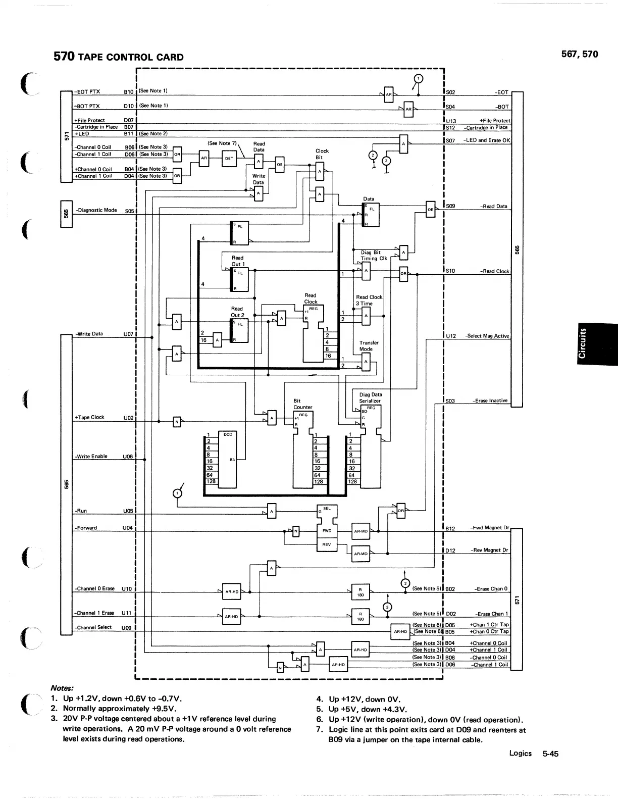
570 TAPE CONTROL CARD
r----------------------------------------,
I
Jp
,
I
,
-
-EOTPTX
Bl0
i
(S
..
Note!)
AR
Iso2
-EOT
r-
010
I (See Note
11
!
-BOTPTX
" AR
Iso4
-BOT
0071
!
+File
Protect
'U13
+File
Protect
-Cartridge
in
Place
B07 S12
-Cartridge.
in
Place
Ii;
+LEO
Bl1
(See Note
21
~
Iso7
B061 (See Note
31
-LED
and
Erase OK
-Channel 0 Coil
(See Note
71
Read
I
Date
Clock
...channel
1
Coil
006
(See Note
31
OR
AR
Bit
,
,
DET
A
OE
~n
,
+Channel 0
Coil
BD41 (See Note
31
I
+Channel 1
Coil
0D4 (See Note
31
OR
Write
,
-
I
Data
I
A
I
I
Data
Iso9
,
1:
FL I
---tf
-Read
Data
I
-Diagnostic Mode
S05
I
!
fl
4
-L
I
I
4
I
..!L.....
I
~
DiagD't
~
I
I Read
Timing
elk
I
F
."
ISIO
-Read
Clock
1
-tl
--LJ
I
'--'
4
I
R
Read
Read
Clock
I
~
~
,~.
I
Read
REG
~
I
Out2
" 1
"A
R
~
A
I
~
f=--_
I
r--
-Write Data U07
~6
A R
-±---
IU12
-Select
Ma.
Active
-¥-
!
4-- Transfer
I
If8
~~
I
~1
I
'---
A
2
I
-
I
I
~
I
Bit
Serializer
IS03
-Erase Inactive
=&=n
REG
-
REG
so
+Tape Clock
U02j
_h
A
+1
G
1
N
R R
1 r-;;co
i"d---
~
p.-
I
t2
I
~
~
~
~
-Write
Enable
U06I
f8
+a-
re----
r;a-
8:':1
t--
'16
I
~
fF
~
I
~
164
164
~
I
9'
'12s
em-
'12a
I
r=_
_f='-
.:.=-
"'----
I
I
SEl
~
-Run
U06I
A G
!
-Forward
UD4
N
FWD
AR-MO
B12
-Fwd
Magnet
Dr
~
I
REV I
AR-MD
i012
-Rev Magnet
Dr
frB
I
¢ I
2 I
-Channel 0 Erase
Ul0
_t"!.
AA.HD
R
(See Note 5) I B02 -Erase Chan 0
'80
~
I
iii
-Channel 1
Erase
Ull
i
AR·HD
R
(See Note
5)
I
002
-Erase Chan 1
uoel
18.
(See Note 6) I
005
-Channel Select
+Chan
1
etf
Tap
AR·HD
(See Note
6~
B05 +Chan 0
Ctr
Tap
-
I
. (See Note
311
BD4
+Channel 0 Coil
I
" A
AR·HD
(See Note 3) I 0D4 +Channel 1 Coil
,
~
(See Note 3) I B06 -Channel 0 Coil
I
(See Note 3) I
006
-Channel 1
Coil
I
I
-
L
______________________________________
~
Notes:
1.
Up
+1.2V, down
+O.6V
to
-O.7V.
4.
Up
+12V, down
OV.
2. Normally approximately +9.5V.
5.
Up
+5V, down
+4.3V_
3.
20V
pop
voltage centered about a
+1
V reference
level
during
write operations. A
20
mV
POP
voltage around a 0 volt reference
level eXists during read operations.
6.
Up
+12V (write operation), down
OV
(read operationl.
7 _ Logic line
at
this point exits card
at
009
and
reenters
at
B09
via
a jumper on
the
tape internal
cable_
Logics 5-45
567,570