EasyManuals Logo

IBM 5100 User Manual

IBM 5100
389 pages
To Next Page IconTo Next Page
To Previous Page IconTo Previous Page
Page #47 background imageLoading...
Page #47 background image
(
f
(
..
\
/
(
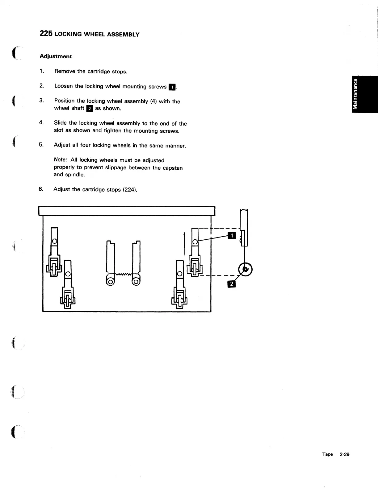
225 LOCKING WHEEL ASSEMBLY
Adjustment
1.
Remove the cartridge stops.
2.
Loosen the locking wheel mounting screws
II.
3. Position the locking wheel assembly
(4)
with
the
wheel shaft
B as shown.
4. Slide the locking wheel assembly
to
the end
of
the
slot
as
shown and tighten the mounting screws.
5.
Adjust all four locking wheels in the same manner.
Note: All locking wheels must
be
adjusted
properly
to
prevent slippage between the capstan
and spindle.
6. Adjust the cartridge stops (224).
Tape 2-29

Table of Contents

Other manuals for IBM 5100

Questions and Answers:

Question and Answer IconNeed help?

Do you have a question about the IBM 5100 and is the answer not in the manual?

IBM 5100 Specifications

General IconGeneral
Release Year1975
RAM16 KB - 64 KB
Storage204 KB tape drive
Display5-inch CRT
Operating SystemAPL/BASIC
ProcessorIBM PALM (1.9 MHz)

Related product manuals