(
(
(
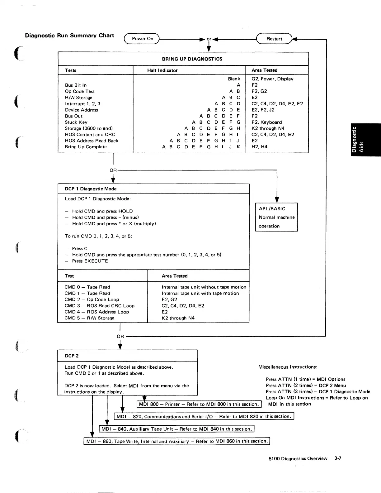
Diagnostic Run Summary
Chart
( Power On
)r-------t.~
~
.------ot,
____
_
BRING UP DIAGNOSTICS
Tests Halt Indicator
Area Tested
Blank G2, Power, Display
Bus Bit In
A F2
Op Code
Test
A
B
F2,G2
RM
Storage A B
C
E2
Interrupt
1,
2,
3 A
B
C 0
C2,C4,D2,D4,E2,F2
Device Address A B C
0 E
E2,F2,J2
Bus
Out
A B C 0 E F
F2
Stuck Key A
B C 0
E F
G
F2,
Keyboar'd
Storage
(0600
to
end)
A
B C 0
E F
G
H
K2
through N4
ROS
Content
and
CRC
A B C 0 E F G
H I
C2,C4,D2,D4,E2
ROS Address Read Back
A
B C 0 E F G H I
J
E2
Bring Up Complete
A B C 0 E
F
G
H
I
J K
H2,H4
I
OR--------------------------------------------,
+
DCP 1 Diagnostic Mode
Load
DCP
1 Diagnostic Mode:
-
Hold
CMD
and
press HOLD
-
Hold CMD and press - (minus)
-
Hold CMD
and
press *
or
X (multiply)
To
run
CMD
0,
1,2,3,4,
or 5:
- Press C
-
Hold
CM
D
and
press
the
appropriate
test
number
(0,
1,
2,
3,
4,
or 5)
- Press EXECUTE
Test Area Tested
CMD
0 - Tape Read Internal tape
unit
without
tape
motion
CMD
1 - Tape Read
Internal
tape
unit
with
tape
motion
CMD
2 - Op Code Loop F2, G2
CMD
3 - ROS Read CRC Loop
C2,C4,
D2,
04,
E2
CMD
4 - ROS Address Loop
E2
CMD 5 -
RM
Storage
K2
through N4
I
APL/BASIC
Normal machine
operation
OR--------------------------------------------------------~
+
DCP2
Load
DCP
1 Diagnostic Model as described above.
Run CMD 0 or 1 as described above.
DCP 2
is
now
loaded. Select
MOl
from
the
menu via
the
instructions on
the
display.
Y
Miscellaneous In
structions:
Press ATTN (
Press ATTN (
Press ATTN (
Loop On
MD
1
time)
=
MOl
Options
2 times)
= DCP 2 Menu
l
MOl
800
- Printer - Refer
to
MOl
800
in
this section
..
J
MOl
in
this
3 times) = DCP 1 Diagnostic Mode
I
Instructions
= Refer
to
Loop
on
section
,
I MOl -
820,
Communications
and
Serial I/O - Refer
to
MOl
820
in
this
section.J
,
I
MOl
-
840,
Auxiliary Tape Unit - Refer
to
MOl
840
in this
section.!
l
MOl
-
860,
Tape Write, Internal
and
Auxiiiary - Refer
to
MOl
860
in this section. I
5100
Diagnostics Overview
3·7