(/
(
c
The data in the character register is decoded
to
select
the correct character
dot
pattern
from
the 2048 x 16K
byte
ROS
on the display card. These
dot
patterns are
serialized by the
10-bit
shift register and placed on the
'-machine
video' line to the display unit. The
'-machine
video' line is controlled by the brightness potentiometer.
Also, the output
of
the
10-bit
shift
register is put on the
'+monitor
video' line
to
the TV monitor.
TV
MONITOR
A separate display unit (TV monitor) can be attached
to
the 5100 through a connector on the back
of
the 5100.
Information is shown simultaneously on the
five-inch
display screen and on the TV monitor.
The
TV
monitor displays the same information
as
the
5100
five-inch
display screen. However, the TV monitor
always has white characters on black background.
2.25V minimum
1.4V m;,;mum
l
1.0V minimum
Ground
When
connected, the TV monitor should provide a
75-ohm
termination load
to
the source ground.
When
several monitors are connected, they should be
connected in parallel fashion, and the last monitor in the
string should be terminated
with
75 ohms. In some
cases, the 5100 might overdrive the TV monitor.
Therefore, the customer
might
have
to
add a
75-ohm
attenuator
to
the rear
of
the 5100.
A composite
video/sync
signal ('+monitor video') is sent
to
the
TV
monitor
through a coaxial cable connected
to
the 5100.
The
TV
monitor has its
own
AC power source and
develops its
own
DC
voltages.
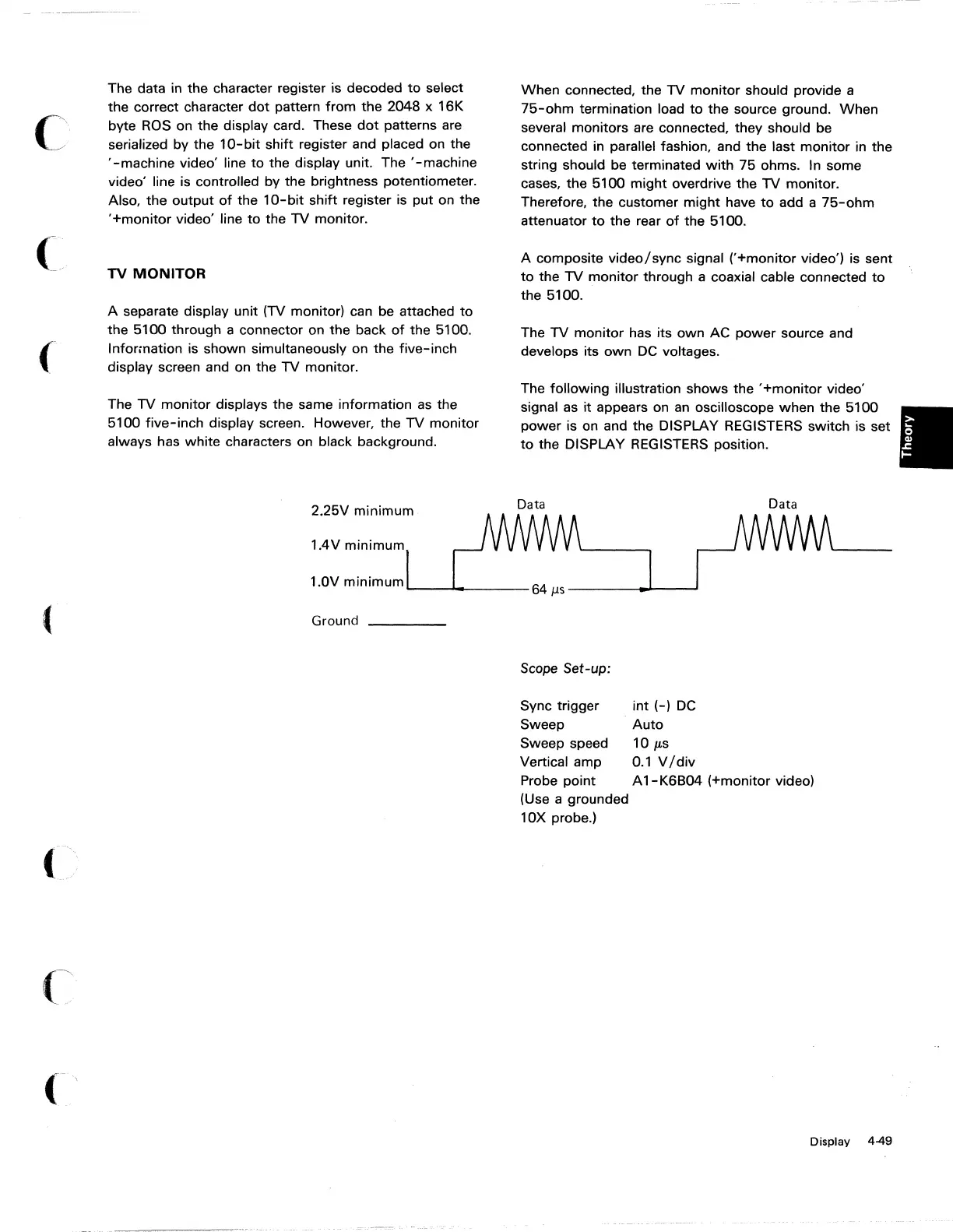
The following illustration shows the
'+monitor
video'
signal as it appears on
an
oscilloscope when the 5100
power is on and the DISPLAY REGISTERS switch is set
to
the DISPLAY REGISTERS position.
Scope
Set-up:
Sync trigger
Sweep
Sweep speed
Vertical amp
Probe point
(Use a grounded
10X probe.)
int
(-)
DC
Auto
10
JLs
0.1
V
/div
A
1-
K6B04 (+monitor video)
Display 4-49