(
(
(
c
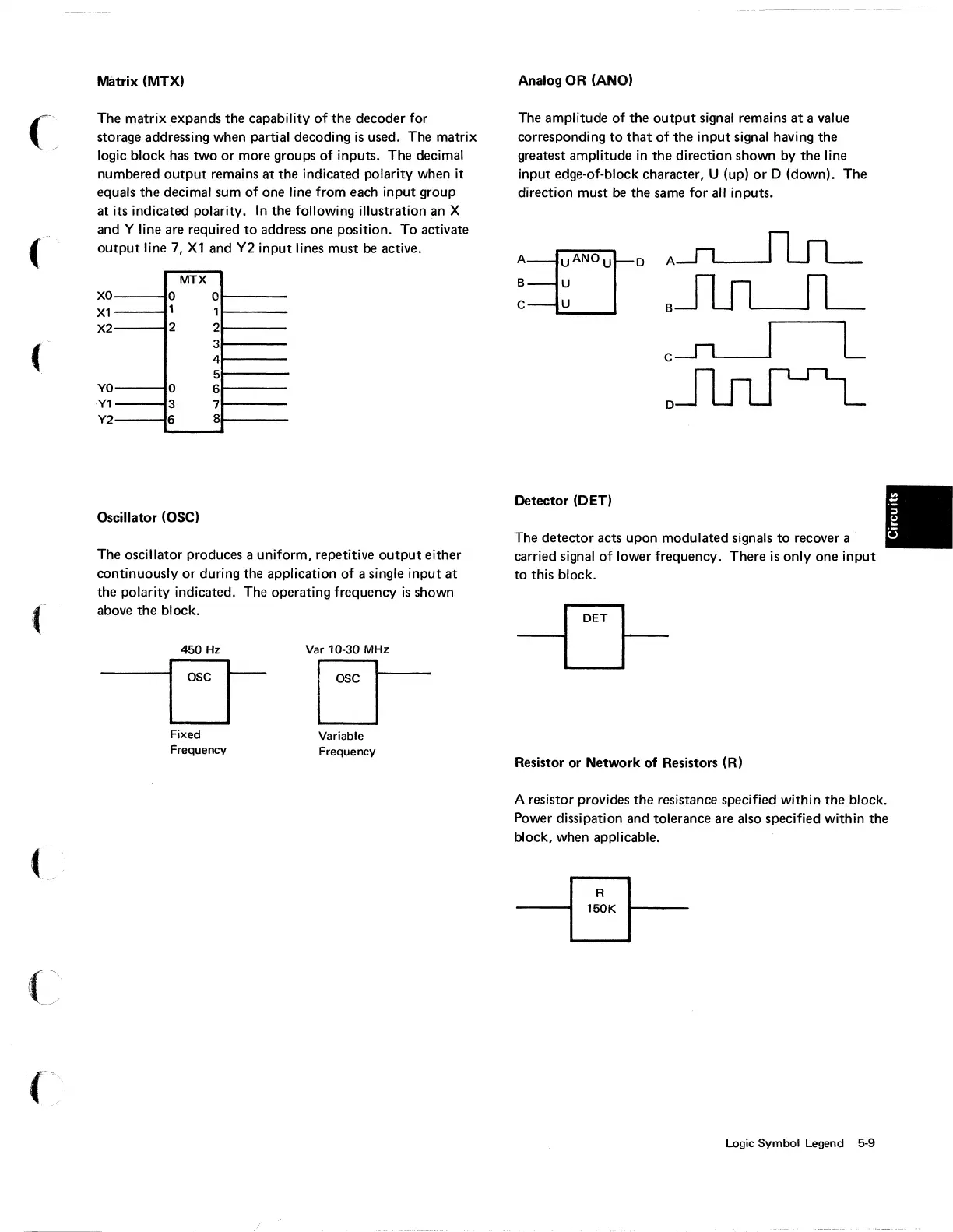
Matrix
(MTX)
The
matrix
expands the capability
of
the decoder
for
storage addressing when partial decoding
is
used. The
matrix
logic
block
has
two
or
more groups
of
inputs. The decimal
numbered
output
remains at the indicated
polarity
when
it
equals the decimal
sum
of
one line
from
each
input
group
at its indicated polarity. In the
following
illustration
an
X
and Y line
are
required
to
address
one position.
To
activate
output
line 7,
Xl
and
Y2
input
lines must be active.
XO
X1
X2
YO
Y1
Y2
0
1
2
0
3
6
MTX
0
1
2
3
4
5
6
7
8
Oscillator (OSC)
The oscillator produces a
uniform,
repetitive
output
either
continuously
or
during the application
of
a single
input
at
the
polarity
indicated. The operating frequency
is
shown
above the block.
450
Hz Var 10-30
MHz
loocr
LJ
Fixed
Frequency
Variable
Frequency
Analog
OR
(ANO)
The amplitude
of
the
output
signal remains
at
a value
corresponding
to
that
of
the
input
signal having the
greatest amplitude in the direction shown by the line
input
edge-of-block character, U (up)
or
D (down). The
direction must
be
the
same
for
all inputs.
An
ANOU
D
B U
C U
Detector (DET)
A~
BJlJLJL
c
-11,-----,1
L
D~
The detector acts upon modulated signals
to
recover a
carried signal
of
lower frequency. There
is
only
one
input
to
this block.
Resistor or Network of Resistors (R)
A resistor provides the resistance specified
within
the block.
Power dissipation and tolerance
are
also specified
within
the
block, when applicable.
Logic
Symbol
Legend 5-9