Exclusive
OR
(OE)
The
output
of an exclusive
OR
block
is
active when only
one of its inputs
is
active.
Time Delay (TO)
The time delay block delays the signal without distorting
the signal. The time delay of the signal
is
above the block.
50
ns
Iml
A--U--
B
Dot
OR
(DOT OR)
This block represents the physical connection
of
the
outputs from
two
or more logic blocks. The polarity of
all
inputs and outputs
is
the same. The DOT
OR
block
represents outputs wired together
to
form the OR function.
In
the following illustration, either
AND
being active causes
the
output
of
the
DOT
OR
to
be minus.
A
A
DOT
OR
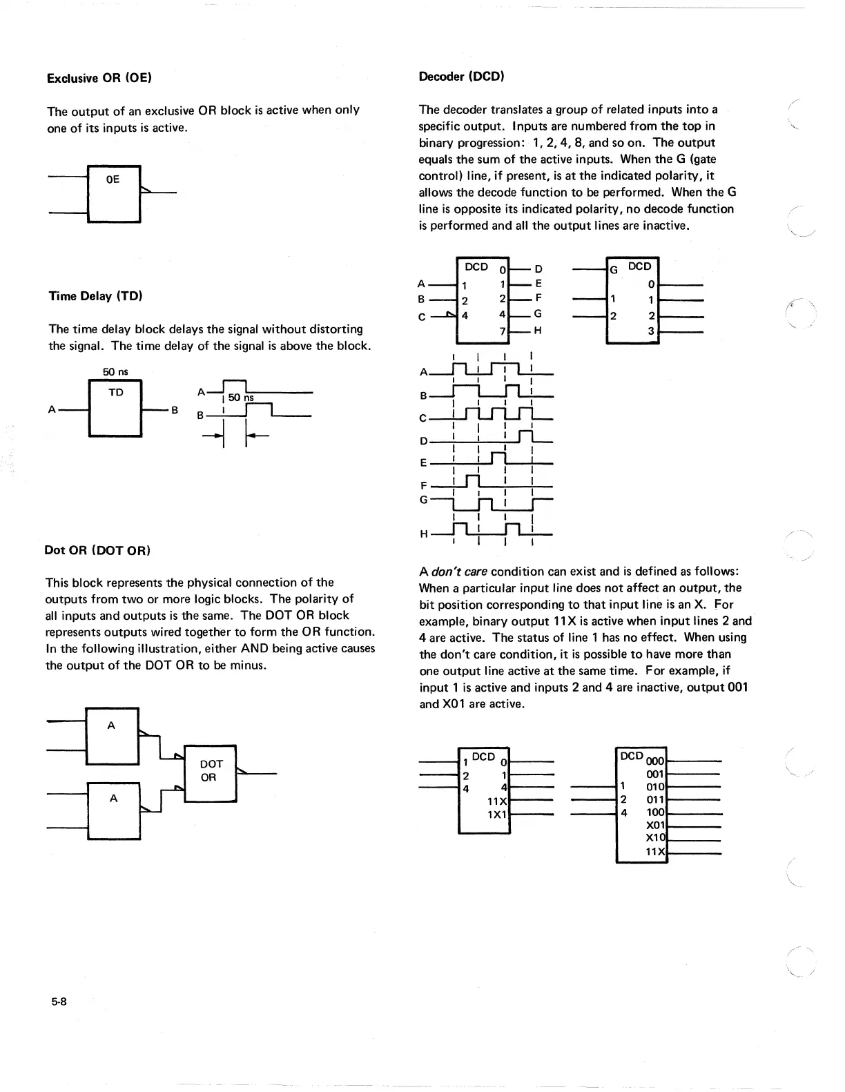
Decoder (OCO)
The decoder translates a group of related inputs into a
specific output. Inputs are numbered from
the
top
in
binary progression: 1, 2, 4, 8, and so on. The
output
equals
the
sum of the active inputs. When
the
G (gate
control) line, if present,
is
at
the indicated polarity, it
allows the decode function
to
be
performed. When
the
G
line
is
opposite its indicated polarity, no decode function
is
performed and
all
the
output
lines are inactive.
DCD
0
D
A
1
1
E
B
2
2
F
C
4
4
G
7
H
I I I I
A~
I I I I
~
B I I I I
~
C I I I I
D I I I
rL-
I I I I
E I I n I
I I I I
F~
I I I I
G~
I I I I
.--Jl...LJl...L
H I I I I
G
DCD
0
2 2
3
A don't
care
condition can exist and
is
defined
as
follows:
When
a particular input line does
not
affect an
output,
the
bit position corresponding
to
that
input line
is
an
X.
For
example, binary
output
11
X
is
active when input lines 2 and
4 are active. The status of line 1 has no effect.
When
using
the
don't
care condition, it
is
possible
to
have more than
one
output
line active
at
the
same time. For example,
if
input 1
is
active and inputs 2 and 4 are inactive,
output
001
and
X01
are active.
1 DCD 0
DCD
OOO
-
2
1
001
4
4
1
010
11X
2
011
1X1
4
100
X01
XH
11X
rf'\
"-