~
'So
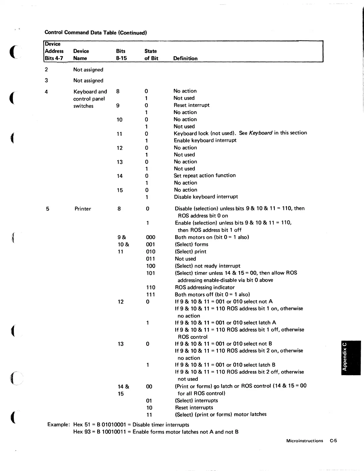
Control Command Data Table (Continued)
(
Device
Address Device Bits
State
Bits
4·7
Name
8·15
of
Bit
Definition
2 Not assigned
3 Not assigned
(
4
Keyboard and
8
0
No
action
control panel
1
Not used
switches
9
0
Reset interrupt
1
No
action
10 0
No
action
1
Not used
11
0
Keyboard lock (not used). See Keyboard
in
this section
Enable keyboard interrupt
12
0
No
action
1
Not used
13 0
No
action
1
Not used
14
0
Set repeat action function
1
No
action
15 0
No
action
Disable keyboard interrupt
5
Printer
8 0
Disable (selection) unless bits 9 & 10 &
11
= 110, then
RDS
address bit 0 on
Enable (selection) unless bits 9 & 10 &
11
= 110,
then
RDS
address bit 1
off
~{
9&
000
Both motors on (bit 0 = 1 also)
10&
001
(Select) forms
11
010
(Select) print
011
Not used
100
(Select) not ready interrupt
101
(Select) timer unless 14 &
15
= 00, then allow
RDS
addressing enable-disable
via
bit 0 above
110
RDS
addressing indicator
111
Both motors off (bit 0 = 1 also)
12 0
If9&
10&
11
=001 or
010
select
not
A
If 9 & 10 &
11
= 110
RDS
address bit
lon,
otherwise
no action
If9&
10&
11
=001 or
010
select latch A
(
If
9 & 10 &
11
= 110
RDS
address bit 1 off, otherwise
RDS
control
13
0
If
9 & 10 &
11
= 001 or 010 select
not
B
If
9 & 10 &
11
= 110
RDS
address bit 2 on, otherwise
no action
1
If9&
10&
11
=001 or
010
select latch B
(/
If
9 & 10 &
11
= 110
RDS
address bit 2 off, otherwise
not
used
14 & 00
(Print or forms)
go
latch or
RDS
control (14 & 15 =
00
15
for
all
RDS
control)
01
(Select) interrupts
10
Reset interrupts
(
11
(Select) (print or forms) motor latches
Example:
Hex
51
= B 01010001 = Disable timer interrupts
Hex
93 = B 10010011 = Enable forms motor latches
not
A and
not
B
Microinstructions
C.s
 Loading...


