c
(
(
(
(
c
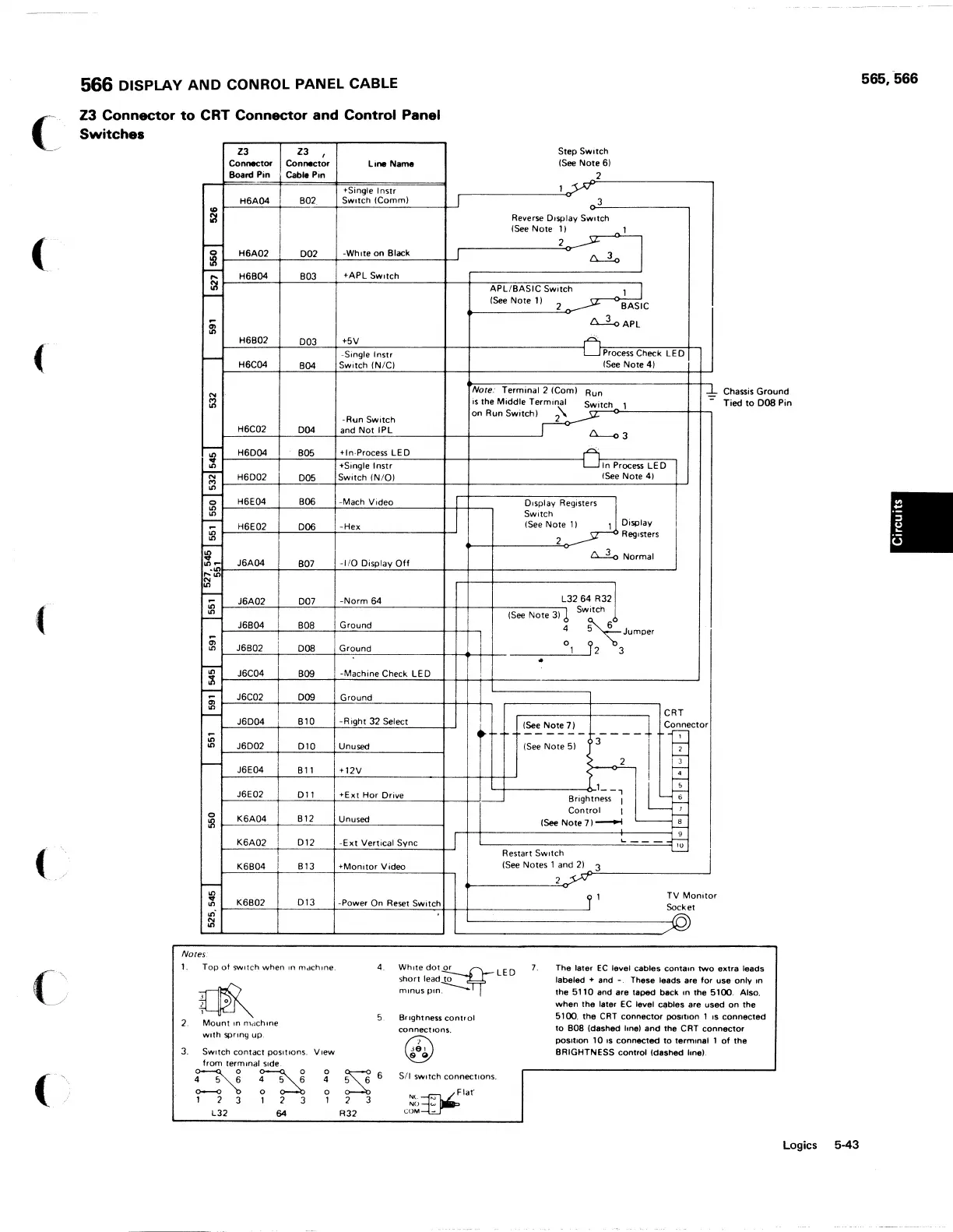
566 DISPLAY
AND
CONROL PANEL CABLE
Z3
Connector
to
CRT
Connector
and
Control
Panel
Switch
••
Z3
Connector
Board Pin
H6A04
Z3 ,
Connector
Cable
Pin
B02
Line Name
tSingle
Inst,
SWitch IComm)
~~~H~6=A~0=2~~~0~0~2--~~-W~h~l~te~0~n~B~I~~k------~
Step Switch
lSee
Note 6)
2
Reverse
Display
SWitch
ISee
Note
1)
1
2
~
~
I
-;:::- H6B04 B03 +APL SWitch
~~~==~+-~~--~~~~~~----~--~--A~Pn.L~/~B~A~S~IC~S~W~i~tC~h--------l--'I
-
t--_lSee
__
N_ot_e_l_)
---,,2'-O'"~~
BASIC
H6B02
003
H6C04
B04
+5V
-Single
I
nstr
Switch
IN/CI
LL!oAPL
Process
Check
LE
0
ISee
Note 4)
Nore: Terminal 2
IComl
is
the Middle Terminal
Run
Switch 1
~
Chassis
Ground
Tied
to
008
Pin
-Run Switch on Run Switch I
2\.
~_H_6_C_0_2
__
~-=0~04~~~a~n~d~N~o=t~I~P=L
________
~~
__________
-J~
~~~H~6~0~04~~
__
=BO~5~-4~+~I~n.~p~ro~c~eS=S~L=E=0~
___
~-4
________
---------4
c..:::....
N
'"
'Single Instr
In
Process
LE
0
~~_H~6_o~0_2_~-=0=0~5
__
~S_W_it~C~h~IN~/O~I~
_____
~~
_____________________
I_Se_e
__
N_o_te_4_1
__
-t-'
~
H6E04
BOO
-Mach Video I
~
~-'-~~-+---=~--+~~~~~------~-+-+--~
"-;:-
H6E02 D06 -Hex
~
r_~~~_t----"~--+~~------------_t~
ISee
Note
11
1 Display
Display
Regj:Jters
Switch
2 Registers
t-----+----~~
~Normal
'i""
""~!r_~J~6~A~04~-+--=B~0~7--~-~I~/O~D~isp~la~y~O~f~f----~--+--~--
________________________
-J
~'"
-;:-
J6A02 D07
-Norm
64
L3264
R321
~t-~::..::~--t---::.=---t~=~-'-----------t-t-t---t----,IS:-ee----:N-o-t-e-::3::-)'
~
Switch 1
J6B04 B08 Ground 4
~Jumper
~
~~J~6B~0=2'--_+i
__
--'D:..:08~_f_G:cr__:o=un"'d=----------_+_+_+_+_+__
____
_.__---°-'-1
-----,y
2 3
~r-~J~6~C~04-'--+--=B~09~_~-~M~a~c~h~in~e~C~h~e~ck~L=E~D--t-~~1~--------._----------------------~
CRT
-;:-
J6C02 D09 Ground
~
t---=='-=--__t----"~--+~~~----------_+_+_+-+_,
-
____
+
c~ector
3 2 I +
lSee
Note
7)
Bl0
-Right
32 Select
J6D04
~
~
J6D02 D 1 0 Unused
~~~+--~~~~~---------~
ISee
Note
51
J6E04
Bll
+12V
I ~
J6E02 011 +Ext Hor Drive
L-1-----------
__
6-
L
_,
t---=='-=--__t----"-'-'---+="-'-'='--"=~----_+--_+_l------l
Brightness I
~+
m
~~K~6=A~0~4~~-=B~1~2--~U~n~u=s~ed~--------~
K6A02
012
-Ext
Vertical
Sync
K6B04 B13
+Monitor
Video
K6B02 D13
-Power On Reset Switch
Control I
--
lSee Note
71
~
'--~
L-
____________________
~~~~~~~
-'-
Restart
SWitch
ISee
Notes 1
2
and
2,.,1
~3'---------------------'
TV
Monitor
Socket
Notes'
1-
Top
of
SWitch
when
In
mdchlne.
~
2
Mount'"
moch me
With
spring up.
3.
SWitch
contact
POSitions. View
from
term Inal
Side
~
~
°
4
0
1 2
3
1 2
3
1
L32
64
4.
5.
~
6
2
3
R32
short
lead
to
Whltedot~LED
mInU5P,"~
Bnghtness
control
connections.
®
Je,
e ~
5/1
SWitch
connections.
Nl.~laf
NO
1.0>
COM
...
7.
The
later
EC
level
cables
contain
two
extra
leads
labeled + and
-.
These leads are
for
use
onlv
In
the 5110
and
are taped back
In
the 5100. Also.
when
the
later
EC
level
coIJbles
are used
on
the
5100,
the
CRT
connector
poSition
1 IS
connected
to
B08
Idashed hnel and the
CRT
connector
poSition
lOIs
connected
to
terminal
1
of
the
BRIGHTNESS control Idashed hnel.
Logics
565,-566
5-43