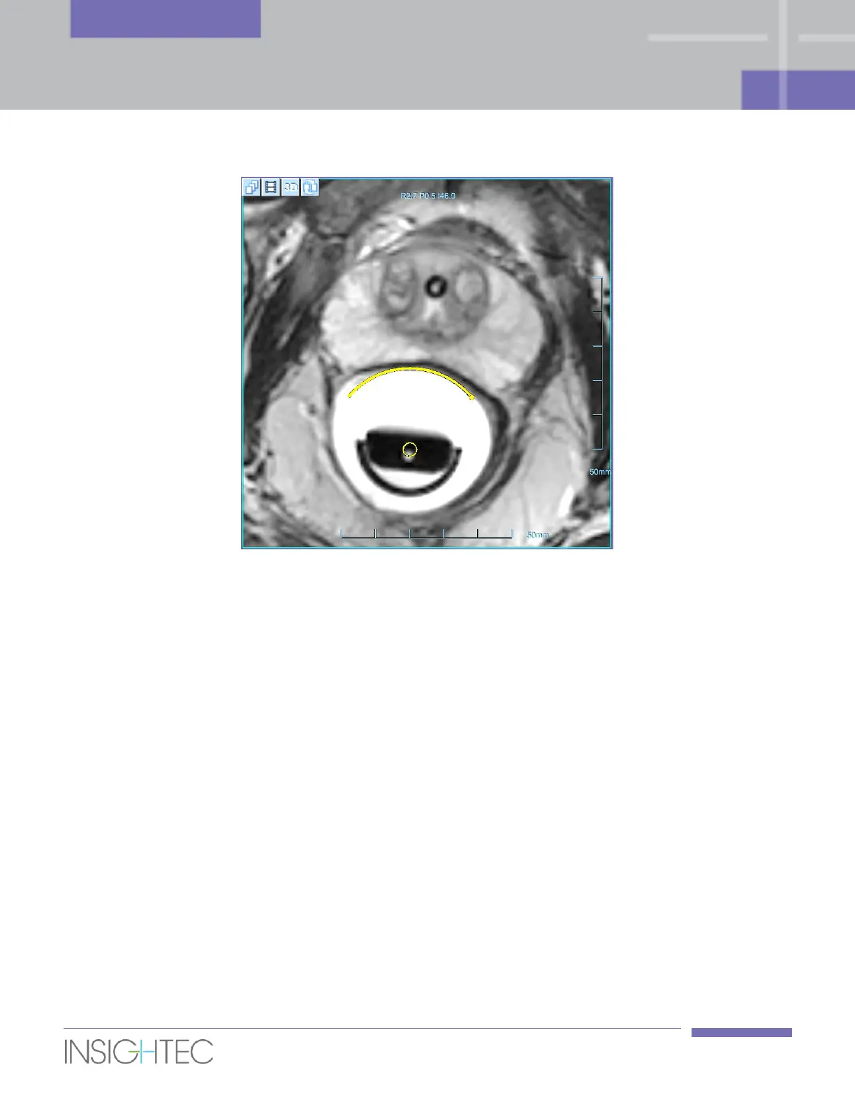
Figure 6-6: Balloon Boundaries (yellow arc)
6.7.6. Draw Limited Energy Density Regions (LEDR’s) - Optional
When there is a need to prevent the predicted dose from reaching sensitive regions, corresponding LEDR
contours should be drawn on all relevant images.
The LEDR’s are optional drawings that mark sensitive structures. They are defined by a safety margin
(measured in millimeters). The system plans and validates spots according to the distance of the predicted
dose from the different LEDR’s.
The following LEDR’s are available for drawing:
◼ Urethra: draw the Urethra LEDR on Axial Planning images. By default, the system will keep the
predicted dose at a safety distance of 3mm from the drawing.
◼ Sphincter (Apex and/or base): draw the Sphincter LEDR on Coronal Planning images. The system
will keep the predicted dose at a safety distance of 5mm from the drawing.
◼ Nerves: draw the Nerves LEDR on Axial Planning images. The system will keep the predicted dose
at a safety distance of 3mm from the drawing.