TREATMENT STAGE
Manual Part Number
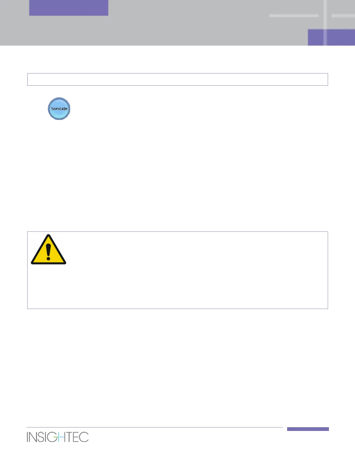
4. Click the Sonicate button to apply the ultrasound energy. The system transfers the
sonication location to the MR.
5. The sonication will start with the MR scanning images and then starts transmitting ultrasound
energy.
During the sonication, the following factors should be monitored:
◼ The evolving temperature rise and dose during sonication.
◼ Patient movements, by observing the Rectal Wall and Prostate Capsule drawings on the updated
MR anatomical images.
◼ The real-time images to ensure coupling and verify no air bubbles entered the interface between the
balloon and the rectal wall.
◼ Spectrum signal during the transmission of the acoustic energy.
◼ In case of an unanticipated system action or patient reaction, the operator, the
nurse or the patient (if applicable) can immediately interrupt the treatment at any
time with the MRI Stop Scan or Stop Sonication buttons.
◼ At any point if any undesired signs appear, the Stop Sonication button must be
pressed immediately.
[W-30]
6. When the thermal imaging is complete after the sonication, the screen is automatically replaced by
the Thermal Evaluation screen (see Figure 7-4).
7. System automatically initiates Current Anatomy Scans on the MR (in the background). The updated
strips will be displayed when returning to the Treatment Main Screen (see Figure 7-1).
7.4.3.2. Geometric Adjustment
The Adjust function enables correction of the transducer’s electronic position according to the offset
between the sonication location and the planned spot location.