3─95
3 Checking Receiver System
The maximum range of the PM pattern on the display indicates that the receiver system’s sensitivity has
reduced.
Check Procedure
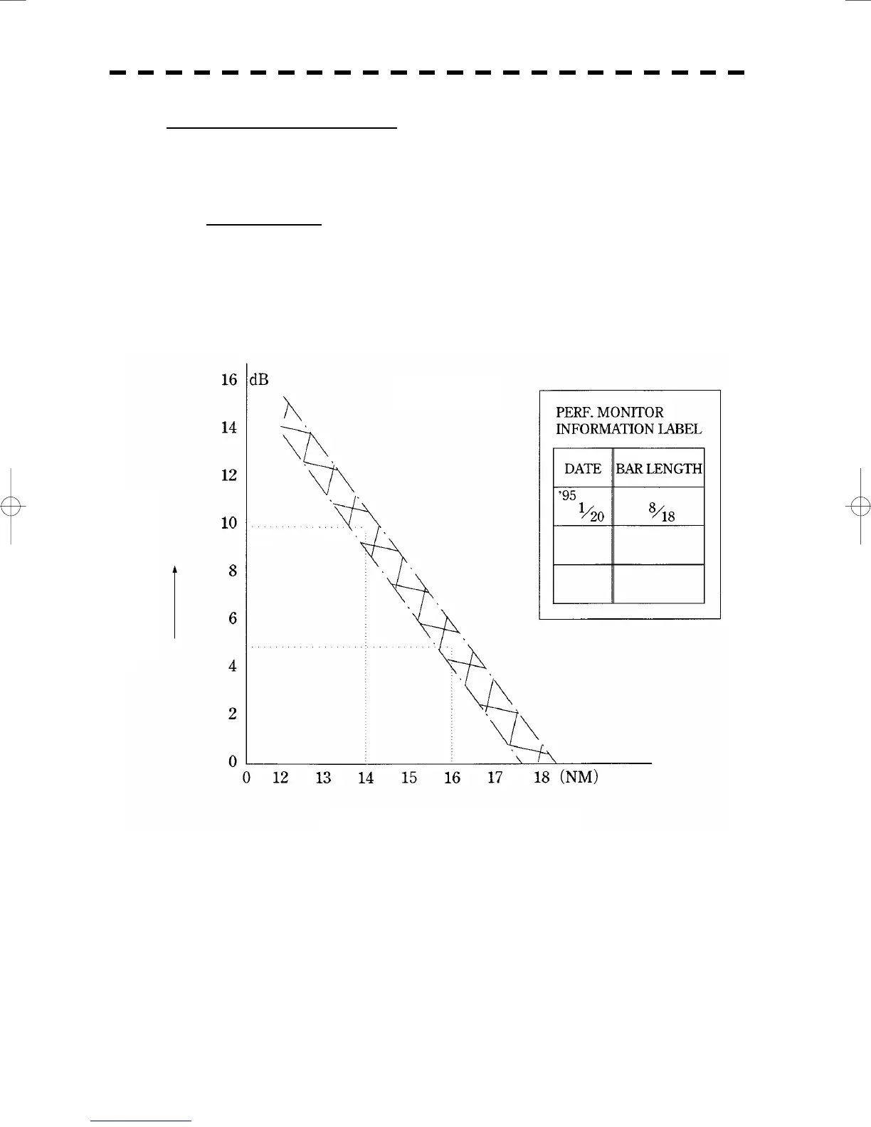
c Measure the maximum range rmax from the PPI center to the PM pattern on the
display by using a VRM (Variable Range Marker).
d Referring to the Calibration Curve II, obtain the reduction of sensitivity R (rmax).
The value R (rmax) indicates the current reduction of receiver system’s sensitivity.
Figure 3
Calibration Curve II
Reduction of Sensitivity R (rmax)
Maximum Range of PM Pattern (rmax)

 Loading...


