2-18
JMA-9100 Instruction Manual > 2.CONTROL PANEL KEYS and SOFTWARE BUTTONS > 2.3 FUNCTIONS OF SOFTWARE
BUTTONS
Interswitch connection change
This button is displayed when the interswitch is connected. This button indicates the
connection status of the scanner unit that is connected to the indicator.
If the button is clicked in the transmission standby state, the menu for changing the
connection state between the scanner unit and the indicator is displayed. The connection
state of the scanner unit and indicator cannot be changed unless the master indicator is in
a standby state.
Refer to the Appendix A NQE-3141 Interswitch Unit Interswitch (Optional) Instruction
Manual that is attached for the setting method. This button is not displayed if the
interswitch is not connected.
Transmission pulse length switching
The transmission pulse length is switched whenever this button is clicked. Three types
of pulses are available, short pulse (SP), middle pulse (MP), and long pulse (LP). The
pulse length and repetition frequency vary even for the same short pulse, according to
the range that is used and it is displayed as , .
Azimuth display mode switching
The azimuth display is switched whenever this button is clicked.
(Head Up) ⇒ (North Up) ⇒ (Course Up) ⇒
If the button is clicked for 2 seconds, the GYTO Setting menu is displayed.
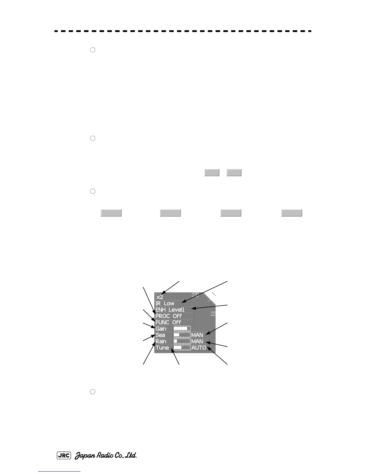
Lower left of the display
Double zoom switching
Use this function to enlarge to double the size the display screen of the position specified
by the cursor. If this button is clicked, the zoom mode is set. When the cursor is moved
to the radar screen and left-clicked, the screen is enlarged to double the size so that the
middle of the cursor and the own ship's position is set to the center of the screen. This
function cannot be used when the range is 0.125NM.
6
7
SP1 SP2
8
H Up N Up C Up H Up
③ Target enhance (ENH)
mode switching
④ Radar video processing (PROC)
mode switching
⑤ Function (FUNC)
mode switching
① Double zoom switching
② Interference rejection (IR)
mode switching
⑦ Sea clutter suppression (Sea)
adjustment
⑧ Rain / snow clutter
suppression (Rain)
adjustment ⑨ Tune adjustment
⑩ Sea clutter suppression (Sea)
mode switching
⑪ Rain and snow clutter
suppression (Rain)
mode switching
⑥ Gain adjustment
⑫ Tune mode switching
1
 Loading...


