8-24
JMA-9100 Instruction Manual > 8.COUNTERMEASURE FOR TROUBLE ... > 8.4 REPLACEMENT OF MAJOR PARTS
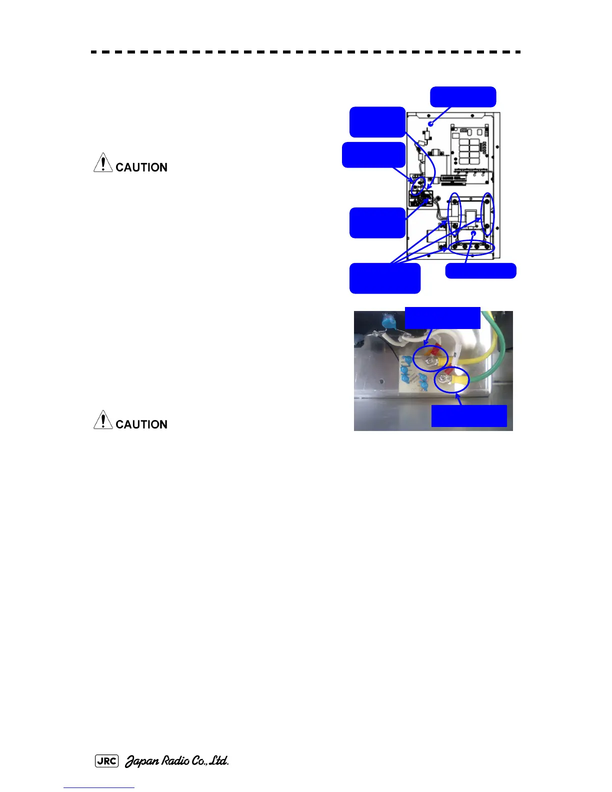
3) Remove the screws holding the cables (two
M4 screws) and the bolts holding the
magnetron (eight M6 screws) and remove the
metal fitting and the magnetron.
Use a non-magnetic screwdriver. If the
magnetron comes into contact with any metal
(tool), its performance may deteriorate.
4) Be careful to attach the colored cables (yellow
and green) to the correct connections on the
replacement magnetron.
After having replaced the magnetron,
reassemble the unit by following the
disassembly procedure in the reverse order.
Do not forget to tighten the bolts and screws, and
do not forget to reconnect the cables.
[Operation check]
After you have completed the replacement work, follow the procedure below to
check the operation.
1) Turn on the power supply for the radar. Allow sufficient time for the radar to be
preheated (about 20 to 30 minutes / bring the radar unit to STBY mode).
2) Start emitting radio waves from the short pulse range and gradually change the
emissions to the long pulse range. Open the service engineer menu to perform tuning
adjustment.
If operation becomes unstable such as the magnetron current is unstable, bring the
radar unit back to STBY mode and restart emission after allowing for an interval of 5
to 10 minutes.
3) Emit radio waves in long pulse range mode for about 15 minutes and reopen the
service engineer menu to perform tuning adjustment.
Yellow
cable
Magnetron
Modulator
Green
cable
Remove the
eight bolts.
Remove the
two screws.
Green cable
Yellow cable
 Loading...


