8-38
JMA-9100 Instruction Manual > 8.COUNTERMEASURE FOR TROUBLE ... > 8.4 REPLACEMENT OF MAJOR PARTS
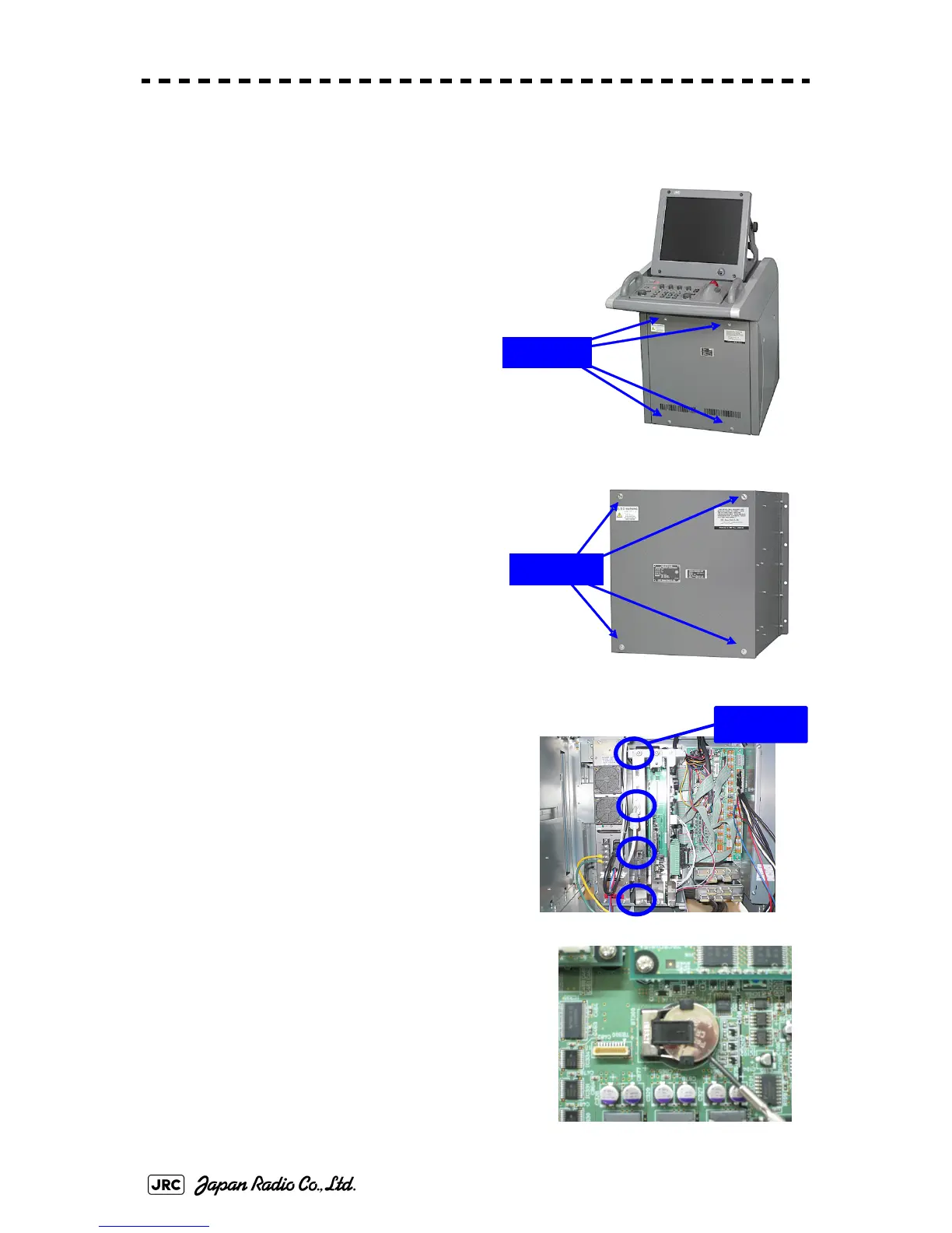
[Disassembly]
1) Remove the four fixing screws to remove
the cover from the display unit (NCD-
4990).
(
A flat tip screwdriver for 6 mm screws
)
For standalone type NCD-4990
For desktop type: NDC-1399-9
2) Remove the cable connected to the radar
process circuit board.
The radar process circuit is the first board from
the left.
3) Remove the two fixing screws (M4).
4) Pull out the board to the front.
5) Insert the flat tip nonconductive screwdriver
for adjustment or some stick between the battery
and the battery holder and lift the battery up.
Remove
Remove
Remove
 Loading...


