A-12
JMA-9100 Instruction Manual > A.NQE-3141 Interswitch Unit > A.3 REFERENCE
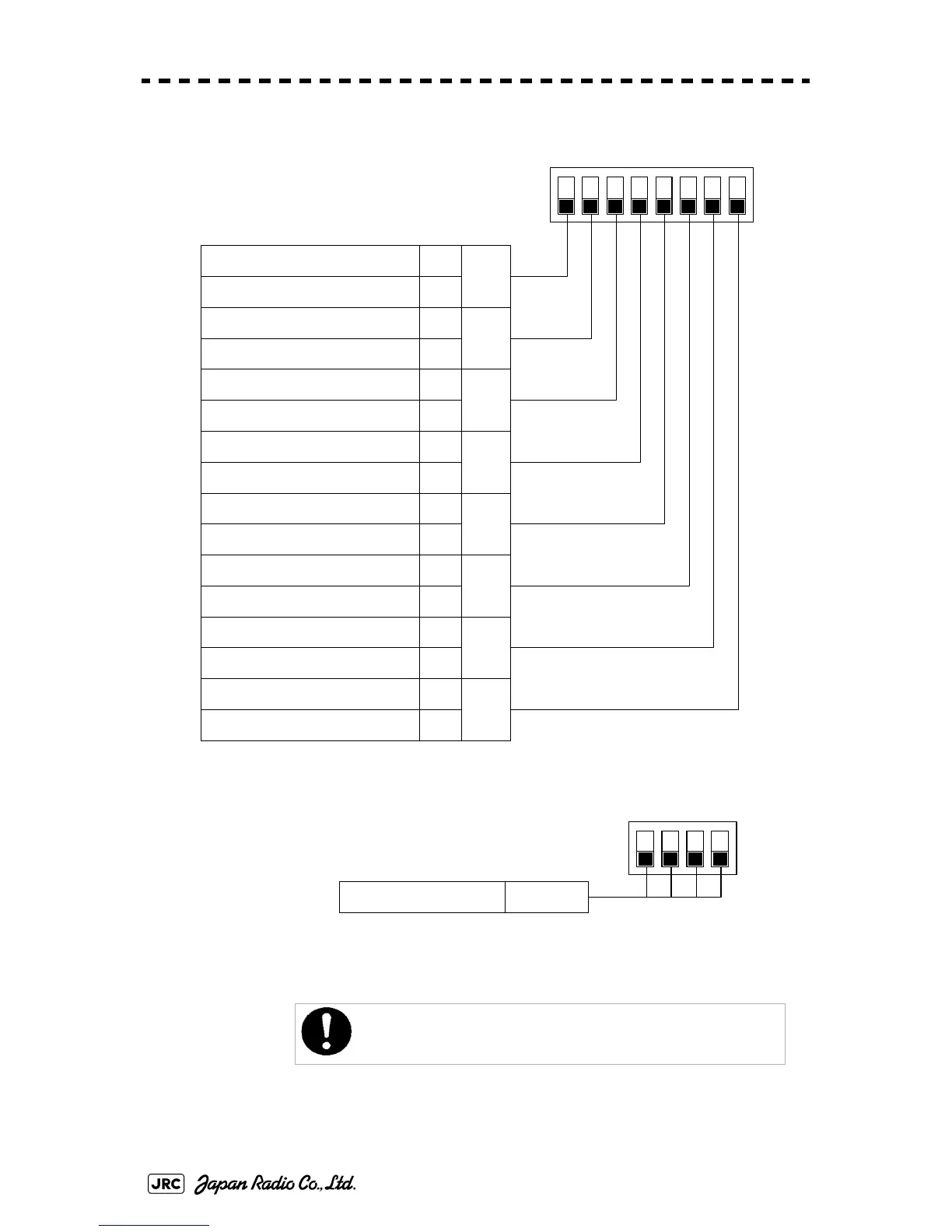
2) SW12 setting (radar connection settings)
3) SW13 (unused)
Before the DIP switches of the interswitch circuit can be set, the
interswitch breaker must be turned off in order to ensure safety
operation.
1
Radar connection settings
ONNo.1 display unit connected
OFFNo.1 display unit NOT connected
2
ONNo.1 scanner unit connected
OFFNo.1 scanner unit NOT connected
3
ONNo.2 display unit connected
OFFNo.2 display unit NOT connected
4
ONNo.2 scanner unit connected
OFFNo.2 scanner unit NOT connected
5
ONNo.3 display unit connected
OFFNo.3 display unit NOT connected
6
ONNo.3 scanner unit connected
OFFNo.3 scanner unit NOT connected
7
ONNo.4 display unit connected
OFFNo.4 display unit NOT connected
8
ONNo.4 scanner unit connected
OFFNo.4 scanner unit NOT connected
1234
ON
OFF
5678
1,2,3,4Unused (All OFF)
1234
ON
OFF
 Loading...


