CAUTION: All QFX5100 switches require two people for installation, one
person to lift the switch into place and another person to attach the switch
to the rack. If you are installing the QFX5100 switch above 60 in. (152.4 cm)
from the floor, you can remove the power supplies and fan modules to
minimize the weight before attempting to install the switch.
CAUTION: If you are mounting multiple switches on a rack, mount the switch
in the lowest position of the rack first. Proceed to mount the rest of the
switches from the bottom to the top of the rack to minimize the risk of the
rack toppling.
Four-Post Procedure
To mount the switch on four posts in a rack using the provided mounting kit:
1. Attach the ESD grounding strap to your bare wrist and to a site ESD point.
2. Decide whether the Field Replaceable Unit (FRU) end of the switch or the port end is
to be placed at the front of the rack. Position the switch in such a manner that the AIR
IN labels on components are next to the cold aisle and AIR OUT labels on components
are next to the hot aisle.
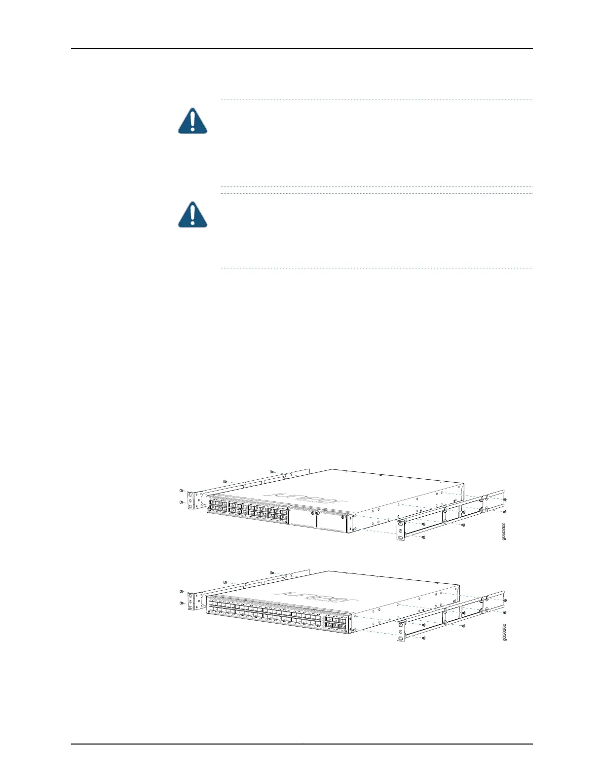
3. Align the holes in the mounting rail with the holes on the side of the chassis. See
Figure 46 on page 162 to see the proper alignment for the QFX5100-24Q switch and
Figure 47 on page 162 for the alignment for the QFX5100-48S switch and
Figure 48 on page 163 for the QFX5100-96S switch.
Figure 46: Attaching Mounting Rails to the QFX5100-24Q
Figure 47: Attaching Mounting Rails to the QFX5100-48S
Copyright © 2016, Juniper Networks, Inc.162
QFX5100 Switch Hardware Guide