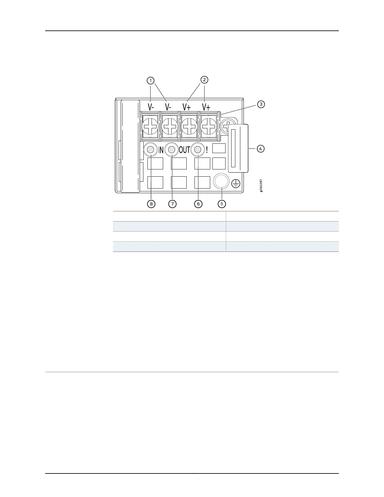
Figure 33: DC Power Supply Faceplate in QFX5100 Devices
5—1— ESD grounding pointFeed B input terminals
6—2— Fault LEDFeed A input terminals
7—3— Output LEDTerminal block
8—4— Input LEDSecurity latch
To avoid electrical injury, carefully follow instructions in “Installing a Power Supply in a
QFX5100 Device” on page 202 and “Removing a Power Supply from a QFX5100 Device”
on page 204.
Related
Documentation
DC Power Supply LEDs on a QFX5100 Device on page 62•
• Management Panel of a QFX5100 Device on page 19
• Field-Replaceable Units in a QFX5100 Device on page 12
• DC Power Specifications for a QFX5100 Device on page 81
• Prevention of Electrostatic Discharge Damage on page 263
• Connecting DC Power to a QFX5100 Device on page 174
Grounding Cable and Lug Specifications for a QFX5100 Device
For installations that require a separate grounding conductor to the chassis, the switch
must be adequately grounded before power is connected to ensure proper operation
and to meet safety and electromagnetic interference (EMI) requirements. To ground a
QFX5100 device, connect a grounding cable to earth ground and then attach it to the
chassis grounding points.
51Copyright © 2016, Juniper Networks, Inc.
Chapter 4: Power Supplies