an optical split cable or a copper DACBO cable. Table 17 on page 60 describes how to
interpret the QSFP+ LEDs.
Table 17: Network Port LEDs on QSFP+ Ports on a QFX5100 Switch
DescriptionStateColor
The port is administratively disabled, there is no power, the link is
down, or there is a fault.
NOTE: When configured for 10-Gigabit Ethernet, the LED remains
unlit only if all four of the 10-Gigabit Ethernet SFP+ breakout links
are down.
OffUnlit
A link is established, but there is no link activity.
NOTE: When configured for 10-Gigabit Ethernet, the LED is lit green
when at least one of the four 10-Gigabit Ethernet SFP+ breakout
links is established.
On steadilyGreen
A link is established, and there is link activity.
NOTE: When configured for 10-Gigabit Ethernet, the LED is lit green
when at least one of the four 10-Gigabit Ethernet SFP+ breakout
links is established.
Blinking
All four LEDs blink to indicate the beacon function was enabled on
the port.
BlinkingAmber
Related
Documentation
Management Panel of a QFX5100 Device on page 19•
• Installing a Transceiver in a QFX Series Device on page 214
• Connecting a Fiber-Optic Cable to a QFX Series Device on page 220
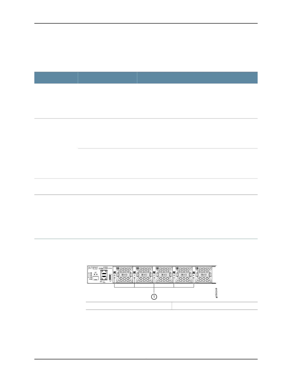
Fan Module LED on a QFX5100 Device
Figure 36 on page 60 shows the location of the LED next to the fan module.
Figure 36: Fan Module LED in a QFX5100 Switch
1— Fan LED
Table 18 on page 61 describes the function of the fan tray LED.
Copyright © 2016, Juniper Networks, Inc.60
QFX5100 Switch Hardware Guide