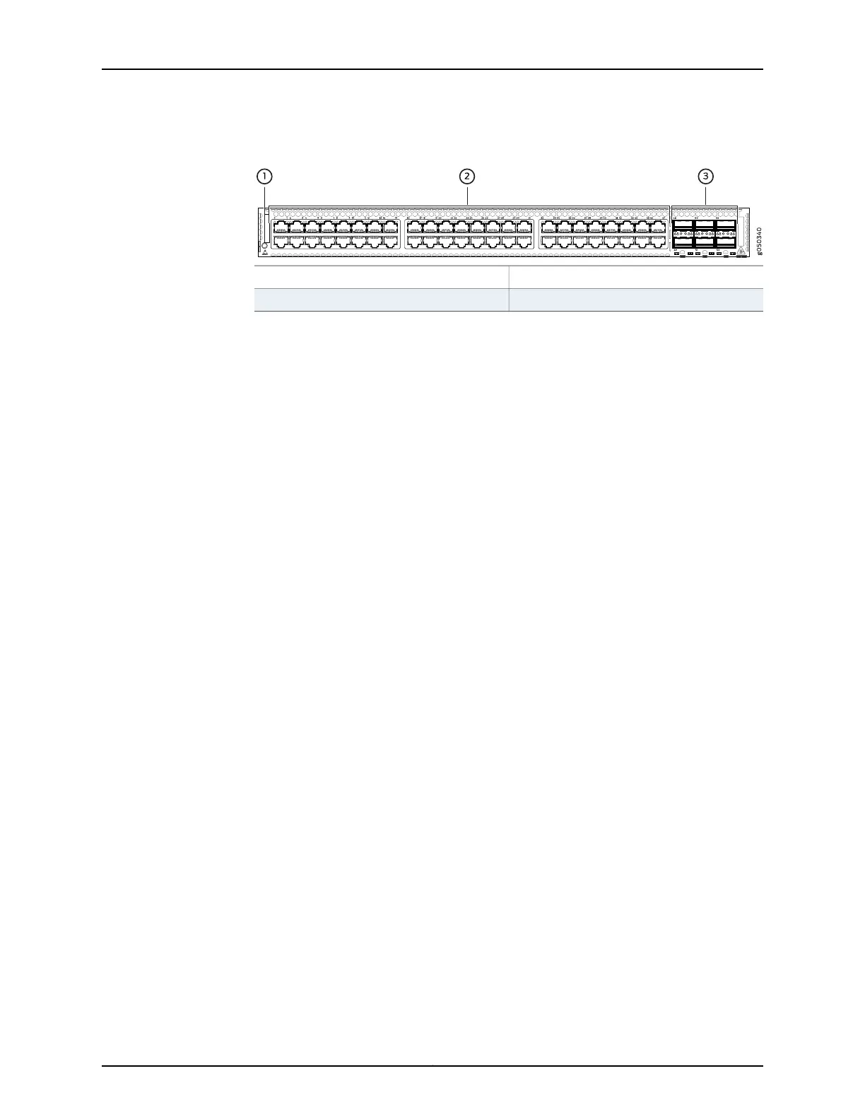
Figure 17: QFX5100-48T Switch Port Panel
3—1— 40 GbE ports (6)Electrostatic Discharge (ESD) terminal
2—10GBASE-T ports (48)
The QFX5100-48T device ports, (0 through 47) support RJ45 connectors. The
QFX5100-48T 40 G uplink or data ports (48 through 53) support:
•
QSFP+ transceivers
•
SFP+ transceivers
•
QSFP+ to QSFP+ direct attach copper (DAC) cables
•
QSFP+ to SFP+ DAC breakout cables (DACBO)
•
QSFP+ to QSFP+ active optical cables (AOC)
•
QSFP+ to SFP+ AOC breakout cables (AOCBO)
To connect a QFX5100-48T switch as a Node device in a QFabric system, you need:
•
Four QSFP+ uplink ports on each QFX5100-48T Node device to connect to the data
plane network through the QFX3008-I or QFX5100-24Q Interconnect devices.
•
The two remaining QSFP+ uplink ports on each QFX5100-48T Node device connect
to the data plane network through the QFX3008-I or QFX5100-24Q Interconnect
devices. See “Interface Specifications for SFP, SFP+, and QSFP+ Transceivers for the
QFX Series” on page 94.
Access port pinouts for the QFX5100-48T switch are the same as the management port
connector pinouts for the QFX Series. For more information, see “Management Port
Connector Pinouts for the QFX Series” on page 85.
Related
Documentation
Access Port and Uplink Port LEDs on a QFX5100 Device on page 57•
• Field-Replaceable Units in a QFX5100 Device on page 12
• Port Panel of a QFX5100-24Q Device on page 23
• Port Panel of a QFX5100-48S Device on page 28
• Port Panel of a QFX5100-96S Device on page 32
• Installing and Removing QFX5100 Device Hardware Components on page 201
• Connecting QFX Series Switches in a Virtual Chassis
• Connecting a QFX5100 Device in a Virtual Chassis Fabric on page 187
• Management Port Connector Pinouts for the QFX Series on page 85
31Copyright © 2016, Juniper Networks, Inc.
Chapter 2: Chassis Components and Descriptions