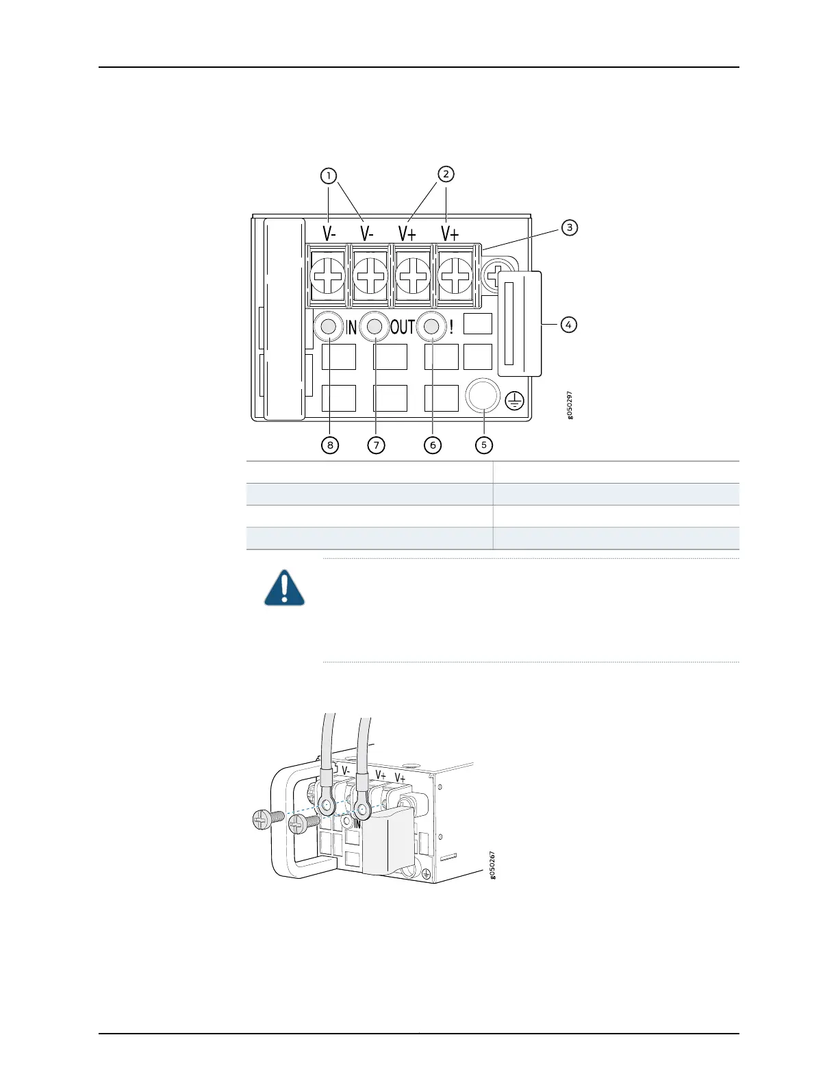
Figure 58: DC Power Supply Faceplate for a QFX5100 Device
5—1— ESD grounding pointShunt negative input terminals (-48V)
6—2— Fault LEDShunt positive input terminals (+RTN)
7—3— Output LEDTerminal block
8—4— Input LEDEjector lever
CAUTION: The V+ terminals are shunted internally together, as are the
V- terminals. The same polarity terminal can be wired together from the
same source to provide an additional current path in a higher power
chassis. Do not connect the terminals to different sources.
Figure 59: Securing Ring Lugs to the Terminals on the QFX5100 DC Power
Supply
8. Replace the terminal block cover.
9. Close the input circuit breaker.
177Copyright © 2016, Juniper Networks, Inc.
Chapter 12: Connecting the Switch to Power