BEST PRACTICE: In a mixed VCF environment with multiple models of
QFX5100 and the EX4300, use QFX5100-24Q as spine devices. In the
maximum configuration of 20 total devices,up to four QFX5100-24Q devices
may be used as spine devices. All members can be connected to the spine
using QSFP+ ports. You can configure the QFX5100-96S as a spine in an all
QFX5100-96S VCF or in a mixed VCF comprised of EX4300 and
QFX5100-96S.
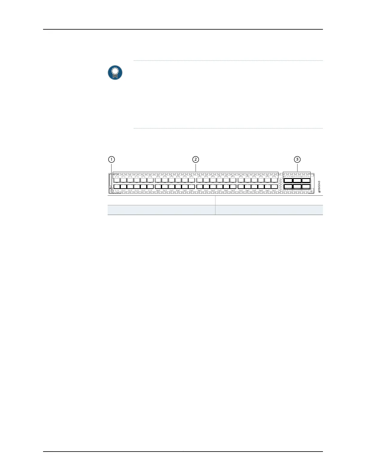
Figure 16 on page 29 shows the port panel of a QFX5100-48S switch.
Figure 16: QFX5100-48S Switch Port Panel
3—1— 40 GbE ports (6)Electrostatic Discharge (ESD) terminal
2—10 G ports (48)
The QFX5100-48S device ports, (0 through 47) support:
•
SFP transceivers that can run at either 100 Mbps or 1 Gbps speed
•
SFP+ transceivers
•
SFP to SFP direct attach copper (DAC) cables
•
SFP+ to SFP+ DAC cables
•
SFP+ to SFP+ active optical cables (AOC)
The QFX5100-48S 40 G uplink or data ports (48 through 53) support:
•
QSFP+ transceivers
•
SFP+ transceivers
•
QSFP+ to QSFP+ direct attach copper (DAC) cables
•
QSFP+ to SFP+ DAC breakout cables (DACBO)
•
QSFP+ to QSFP+ active optical cables (AOC)
•
QSFP+ to SFP+ AOC breakout cables (AOCBO)
Related
Documentation
Field-Replaceable Units in a QFX5100 Device on page 12•
• Port Panel of a QFX5100-24Q Device on page 23
• Port Panel of a QFX5100-96S Device on page 32
• Access Port and Uplink Port LEDs on a QFX5100 Device on page 57
• Installing and Removing QFX5100 Device Hardware Components on page 201
29Copyright © 2016, Juniper Networks, Inc.
Chapter 2: Chassis Components and Descriptions