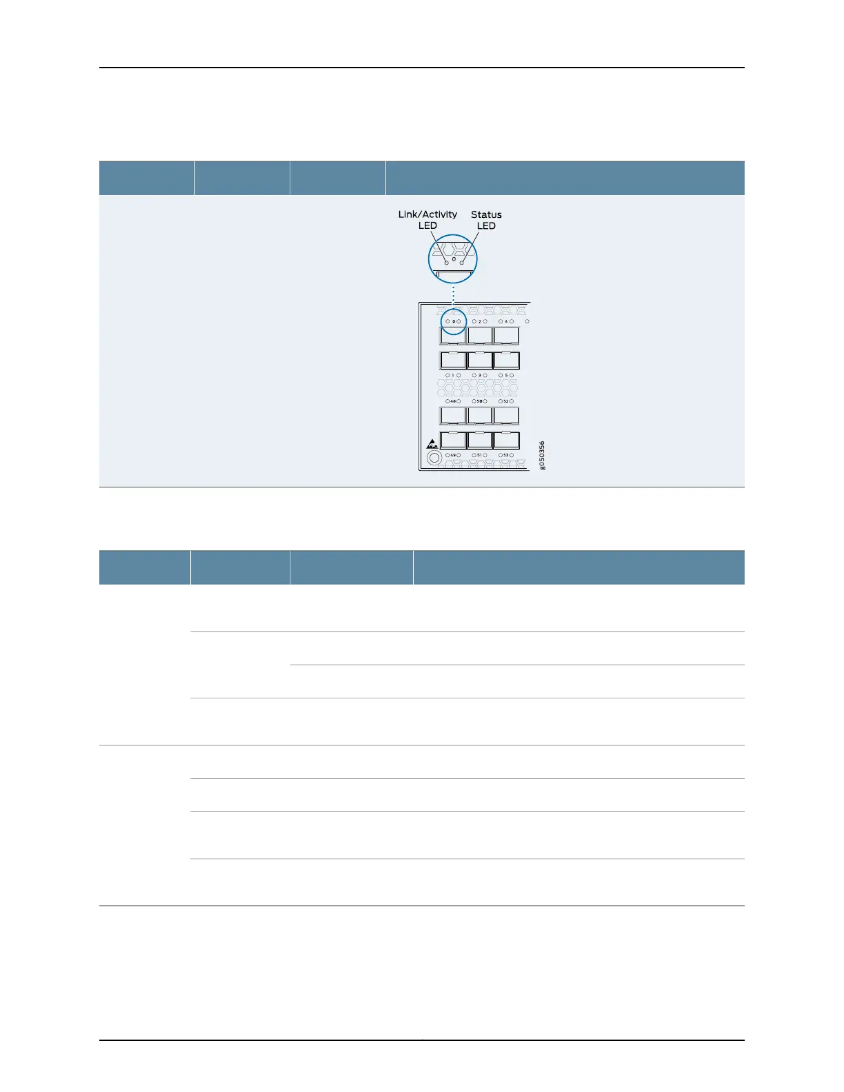
Table 15: QFX5100 Access Port and Uplink LED Locations (continued)
LocationIndicatorsPort TypeModel
Table 16 on page 59 describes how to interpret the SFP+ port LEDs.
Table 16: Network Port LEDs on SFP+ Ports on a QFX5100 Switch
DescriptionStateColorLED
The port is administratively disabled, there is no power, the link
is down, or there is a fault.
OffUnlitLink/Activity
A link is established, but there is no link activity.On steadilyGreen
A link is established, and there is link activity.Blinking
The beacon isenabled onthe port. On QFX5100-48T, it indicates
a fault.
BlinkingAmber
The link is down.OffUnlitStatus
NOTE: Not
applicable for
QFX5100-48T.
The beacon function is enabled on the port.BlinkingAmber
A 1-Gigabit Ethernet transceiver is installed in the port and the
link is established.
BlinkingGreen
A 10-Gigabit Ethernet transceiver is installed in the port and link
is established.
On steadilyGreen
As shown in Table 15 on page 58, there are four bi-color LEDs for each QSFP+ port. The
first LED is used and the remaining LEDs are not used when the interface is configured
for 40-Gigabit Ethernet and connected to a QSFP+ transceiver. All four LEDs are used
when the interface is configured for 10-Gigabit Ethernet and the port is connected using
59Copyright © 2016, Juniper Networks, Inc.
Chapter 5: Viewing System Information