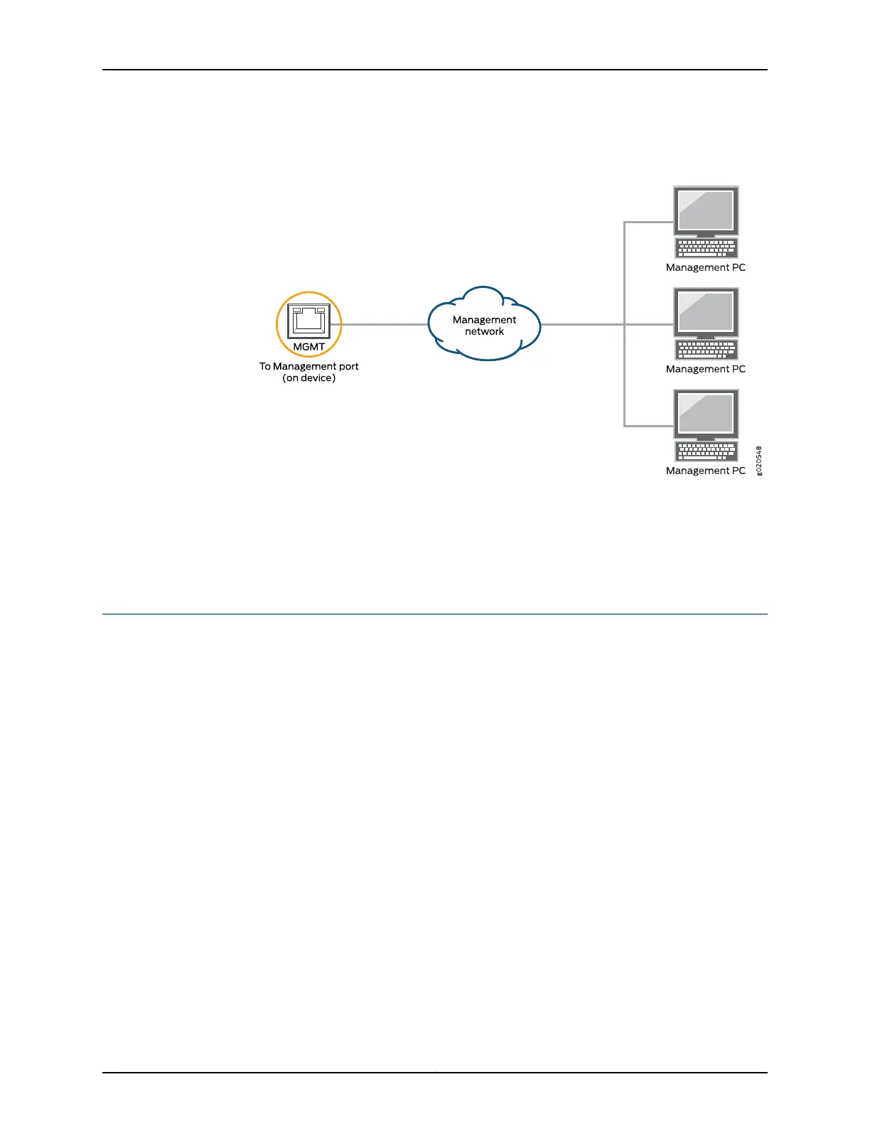
Figure 62: Connecting a QFX5100 Switch to a Network for Out-of-Band
Management
Related
Documentation
Management Panel of a QFX5100 Device on page 19•
• Management Port Connector Pinouts for the QFX Series on page 85
• Connecting a QFX Series Device to a Management Console on page 179
Connecting QFX Series and EX Series Switches in a QFX Virtual Chassis
In a QFX Virtual Chassis, you can connect up to 10 standalone QFX5100, QFX3600,
QFX3500, and EX4300 switches into a QFX Series Virtual Chassis and manage the
interconnected switches as a single chassis. Unlike a Virtual Chassis Fabric (VCF), which
is cabled in a spine and leaf topology, the QFX Virtual Chassis is cabled in a ring topology.
For Virtual Chassis Fabric cabling examples, see “Connecting a QFX5100 Device in a
Virtual Chassis Fabric” on page 187. This topic describes how to cable QFX Series switches
and EX4300 switches into a QFX Virtual Chassis.
•
Before You Start on page 181
•
Valid Configurations on page 182
•
Cabling QFX3500 Switches in a QFX Virtual Chassis on page 183
•
Cabling QFX3600 Switches in a QFX Virtual Chassis on page 184
•
Cabling a Mixed QFX Virtual Chassis on page 185
Before You Start
You configure a QFX Series Virtual Chassis by configuring the switch interfaces into Virtual
Chassis ports (VCPs). VCPs connect switches together to form a Virtual Chassis, and
are responsible for passing all data and control traffic between member switches in the
Virtual Chassis. All non-channelized QSFP+ uplink interfaces on standalone QFX5100
181Copyright © 2016, Juniper Networks, Inc.
Chapter 13: Connecting the Switch to the Network