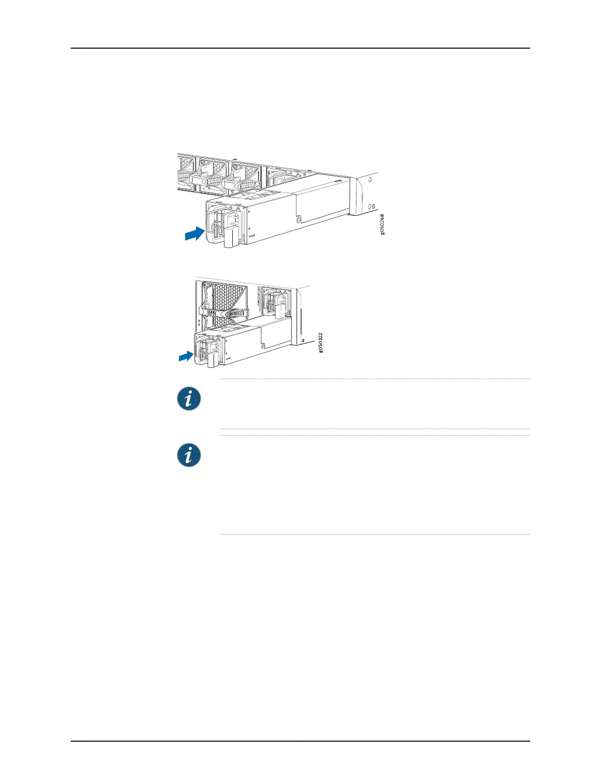
3. Using both hands, place the power supply in the power supply slot on the FRU panel
of the switch and slide it in until it is fully seated and the locking lever slides into place.
Figure 74: Installing a Power Supply in a 1 U QFX5100 Device
QFX5100-48S
RUNNING JUN O S
Figure 75: Installing a Power Supply in a QFX5100-96S Device
NOTE: Each power supply must be connected to a dedicated power source
outlet.
NOTE: If you have a Juniper Care service contract, register any addition,
change, or upgrade of hardware components at
https://www.juniper.net/customers/support/tools/updateinstallbase/ . Failure
to do so can result in significant delays if you need replacement parts. This
note does not apply if you replace existing components with the same type
of component.
Related
Documentation
AC Power Supply for a QFX5100 Device on page 47•
• Field-Replaceable Units in a QFX5100 Device on page 12
• Port Panel of a QFX5100-48S Device on page 28
• Management Panel of a QFX5100 Device on page 19
• AC Power Cord Specifications for a QFX Series Device on page 80
• Connecting AC Power to a QFX5100 Device on page 171
• Connecting DC Power to a QFX5100 Device on page 174
• Removing a Power Supply from a QFX5100 Device on page 204
203Copyright © 2016, Juniper Networks, Inc.
Chapter 17: Replacing Power Supply