Models 2510 and 2510-AT User’s Manual Status Structure 7-13
Operation event register
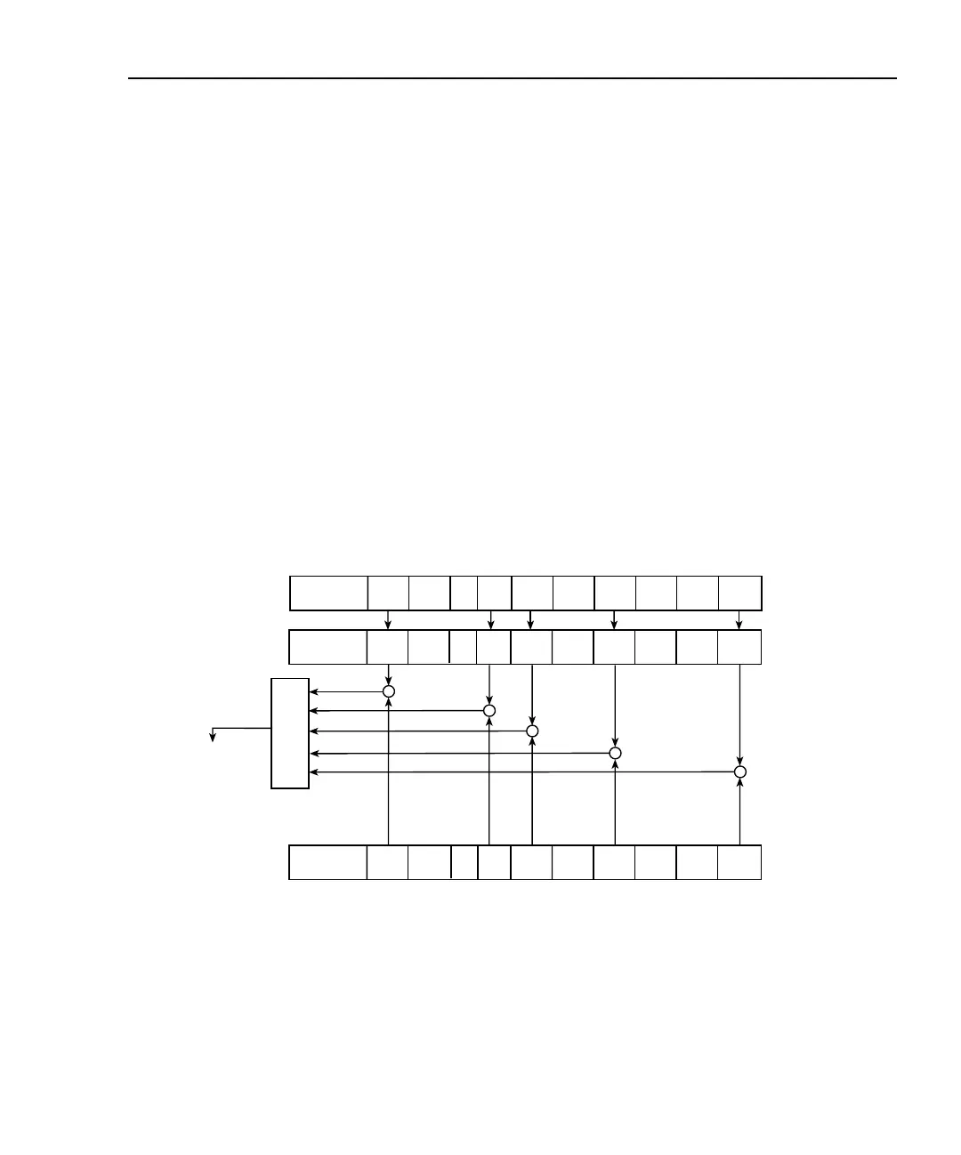
The used bits of the Operation Event Register (shown in Figure 7-5) are described as fol-
lows:
• Bit B0, Calibrating (Cal) — Set bit indicates that the Model 2510 is calibrating.
• Bits B1 through B4 — Not used.
• Bit B5, Waiting for Trigger Event (Trig) — Set bit indicates that the Model 2510
is in the trigger layer waiting for a trigger event to occur.
• Bit B6, Waiting for Arm Event (Arm) — Set bit indicates that the Model 2510 is
in the arm layer waiting for an arm event to occur.
• Bit B7, Autotune Complete (Atc) — Set bit indicates that the autotune process
has been completed (Model 2510-AT only).
• Bits B8 and B9 — Not used (always 0).
• Bit B10, Idle State (Idle) — Set bit indicates the Model 2510 is in the idle state.
• Bits B11 through B14 — Not used.
• Bit B15 — Always zero.
Figure 7-5
Operation event status
Operation
Condition Register
Operation
Event Register
Operation
Event Enable
Register
&
&
&
&
&
OR
To Operation
Summary Bit
(OSB) of Status
Byte Register.
(See Figure 7-1.)
:stat:oper:cond?
Idle = In idle state
Arm = Waiting for arm event
Trg = Waiting for trigger event
Cal = Calibrating
Atc = Autotune complete (Model 2510-AT only)
& = Logical AND
OR = Logical OR
:stat:oper?
:stat:oper:enab<NRf>
:stat:oper:enab?
—
(B1)
—
(B3)
—
(B2)
Cal
(B0)
—
(B4)
Trig
(B5)
Arm
(B6)
—
(B9,B8)
Idle
(B10)
—
(B15 - B11)
—
(B1)
—
(B3)
—
(B2)
Cal
(B0)
—
(B4)
Trig
(B5)
Arm
(B6)
Idle
(B10)
—
(B15 - B11)
—
(B1)
—
(B3)
—
(B2)
Cal
(B0)
—
(B4)
Arm
(B6)
Idle
(B10)
—
(B15 - B11)
Trig
(B5)
Atc
(B7)
—
(B9,B8)
Atc
(B7)
—
(B9,B8)
Atc
(B7)