5-4 Digital I/O Port and Output Enable Models 2510 and 2510-AT User’s Manual
Source operation
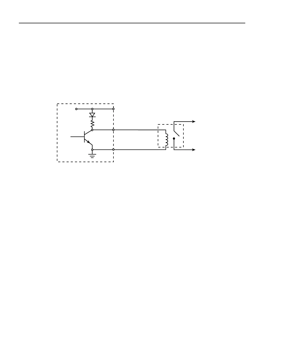
Figure 5-3 shows the basic output configuration for source operation. In this case, the
external relay coil is connected between the digital output line (pins 1 to 4) and ground
(pin 9). With this configuration, the digital output line must be set HI to energize the relay,
and the maximum source current is 2mA.
Figure 5-3
Source operation
Controlling digital output lines
Set digital output line logic levels from the front panel as follows:
1. Press the MENU key.
2. Select GENERAL, then press ENTER.
3. Select DIGOUT, then press ENTER.
4. Using the EDIT keys, set the digital output parameter to the desired decimal value
(Table 5-1), then press ENTER. For example, to set the output lines to L, H, H, H,
set the digital output parameter value to 7, then press ENTER.
5. Press EXIT to return to normal display.
Model 2510
External
Relay
To Other
Circuits
+5V
Maximum Source Current: 2mA
Pin 7
Pins 1-4
Pin 9
Digital I/O
Port