2-2 Connections Models 2510 and 2510-AT User’s Manual
Input/output connections
Input/output connector
The input/output connector is located on the rear panel (see Figure 2-1 and Figure 2-2).
Terminals include:
• OUTPUT terminals: F+, F- (force), S+, and S- (sense) connections to thermoelec-
tric cooler.
• INPUT terminals: F+, F- (force), S+, and S- (Kelvin sense) connections to temper-
ature sensor.
Use the supplied mating connector for connections (Keithley part number CS-846).
NOTE The Model 2510 assumes that a positive output current is a heating current.
2-wire connections
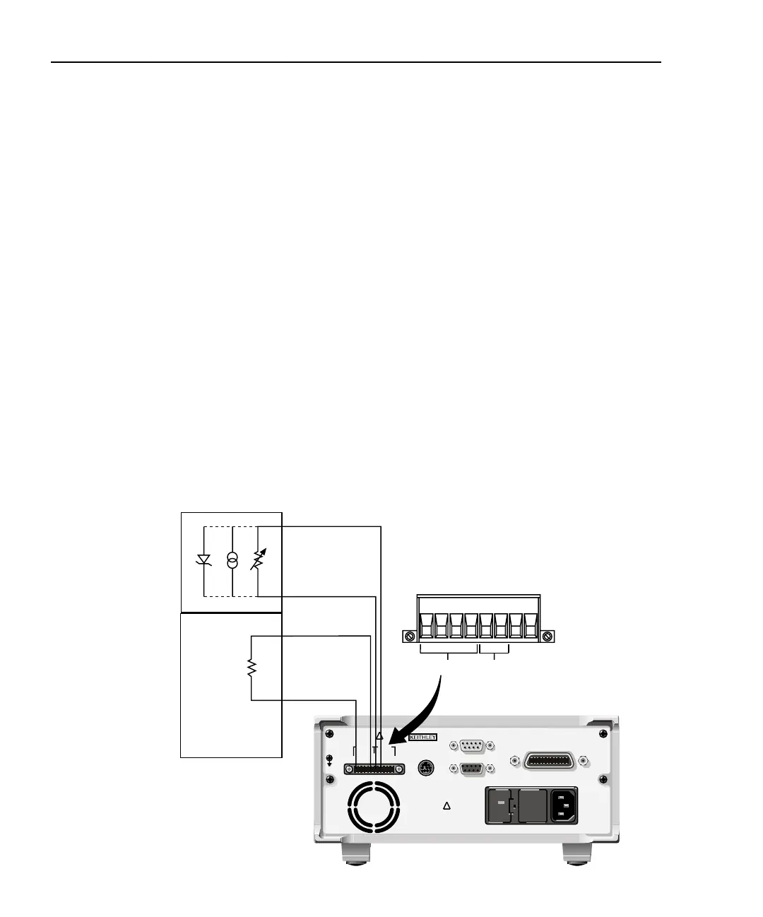
Figure 2-1 shows basic 2-wire signal connections. Note that the OUTPUT F (force) termi-
nals are connected to the thermoelectric cooler (TEC), while the INPUT F terminals are
connected to the temperature sensor. 2-wire sensor connections are recommended for:
• Thermistor and RTD sensors with ≥1kΩ resistance.
• Both AD590 current and LM335 voltage type solid-state sensors.
Figure 2-1
2-wire input/output connections
Model 2510
INPUT F -
INPUT F +
+
-
OUTPUT F -
-
OUTPUT F +
+
TEC
RTD, Thermistor, or Solid-State
Temperature Sensor
Mating Connector
F+ F- F+ F-
Output
Input
R
T
+
-
LM335 AD590
R
T
= Thermistor or RTD sensor
LM335 = Voltage solid-state sensor
AD590 = Current solid-state sensor
WARNING:NO INTERNAL OPERATOR SERVICABLE PARTS,SERVICE BY QUALIFIED PERSONNEL ONLY.
WARNING:NO INTERNAL OPERATOR SERVICABLE PARTS,SERVICE BY QUALIFIED PERSONNEL ONLY.
CAUTION:FOR CONTINUED PROTECTION AGAINST FIRE HAZARD,REPLACE FUSE WITH SAME TYPE AND RATING.
CAUTION:FOR CONTINUED PROTECTION AGAINST FIRE HAZARD,REPLACE FUSE WITH SAME TYPE AND RATING.
120
LINE RATING
100-240VAC
50, 60 HZ
90VA MAX
LINE FUSE
SLOWBLOW
2.5A, 250V
!
!
CAT I
IEEE-488
(ENTER IEEE ADDRESS
WITH FRONT PANEL MENU)
MADE IN
U.S.A .
ENABLE-DIG I/O
RS-232
TRIGGER
LINK
OUTPUT INPUT
F+ S+ S- F- F+ F- S+ S-
ISOLATION FROM EARTH: 30V MAX.
Note: These connections
assume positive
current heats TEC.