Models 2510 and 2510-AT User’s Manual Digital I/O Port and Output Enable 5-3
Output enable line
The output enable line is intended for use with a test fixture to disable the output when the
protection lid is open. See “Output enable line,” page 5-6, for details.
+5V output
The Digital I/O Port provides a +5V output that can be used to drive external logic cir-
cuitry. Maximum current output for this line is 600mA. This line is protected by a self-
resetting fuse (one hour recovery time).
Digital output configuration
There are two basic methods to connect external components to the digital output lines,
sink operation, and source operation.
Sink operation
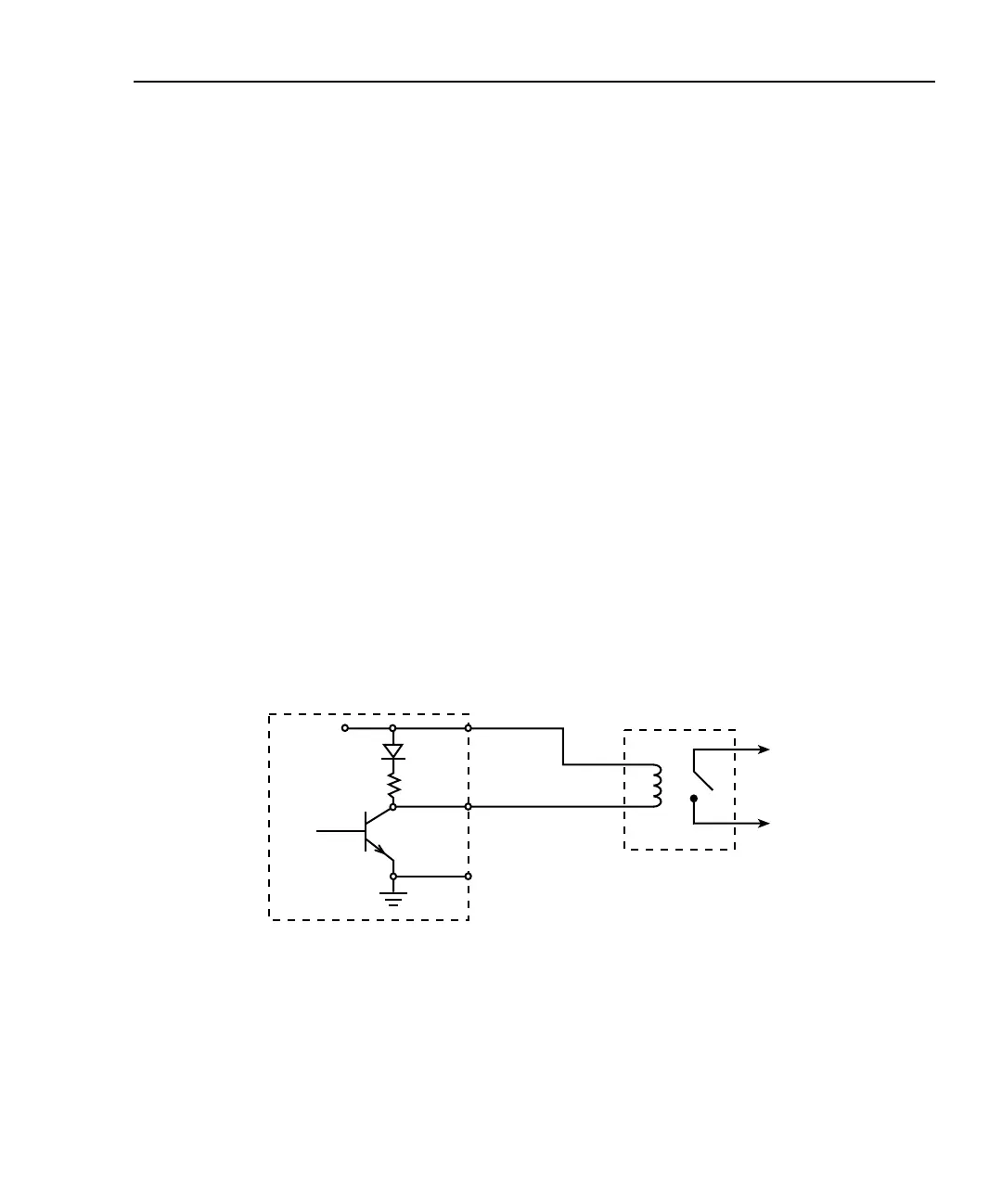
Figure 5-2 shows the basic output configuration for sink operation. Note that the external
relay coil is connected between the digital output line (pins 1 to 4) and +5V (pin 7). With
this configuration, the digital output line must be set LO to energize the relay, and the
maximum sink current is 500mA.
Figure 5-2
Sink operation
Model 2510
External
Relay
To Other
Circuits
+5V
Maximum Sink Current: 500mA
Pin 7
Pins 1-4
Pin 9
Digital I/O
Port