Models 2510 and 2510-AT User’s Manual Getting Started 1-15
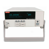
ON/OFF indicator
The ON/OFF indicator shows when the source output is turned on. This indicator will
glow with different colors depending on the following conditions:
• Red = heating (+Peltier voltage)
• Green = cooling (-Peltier voltage)
• Red and green both on (yellow) = voltage overflow (not voltage limit).
EDIT keys
The EDIT keys allow you to program setpoint and other values, and scroll through menu
selections as follows:
• When programming setpoint or other values, use the and keys to increment
and decrement values; use the left and right arrow keys to select the cursor posi-
tion. Pressing any one of these keys enters the setpoint editing mode for the
selected function.
• When scrolling through menu selections, use the and keys to choose specific
items.
See “Menus,” page 1-19, for more details.
Status and error messages
During Model 2510 operation and programming, you will encounter a number of front
panel messages. Status and error messages are displayed momentarily. See Appendix B
for a list of status and error messages and ways to fix common errors.
Front panel tests
Use the TEST/DISPLAY-TESTS selection of the main MENU to test various aspects of
the front panel. Test selections include:
• KEYS – Front panel keys are tested. Pressing a key displays a message that identi-
fies that key. Pressing EXIT twice cancels this test.
• DISPLAY PATTERNS – Use this selection to turn on all display pixels and annun-
ciators. Subsequent keypresses cycle through tests that turn off annunciators and
corner pixels of each digit, turn on the rows of the top-left display digit, and turn on
all annunciators and pixels of each digit in a sequential manner. Press EXIT to can-
cel this test.
• CHAR SET – This test displays special characters. Press EXIT to cancel the test.
See “Menus,” page 1-19, for more menu information.

 Loading...