6-4 Remote Operations Models 2510 and 2510-AT User’s Manual
GPIB connections
To connect the Model 2510 to the GPIB bus, use a cable equipped with standard IEEE-488
connectors as shown in Figure 6-1.
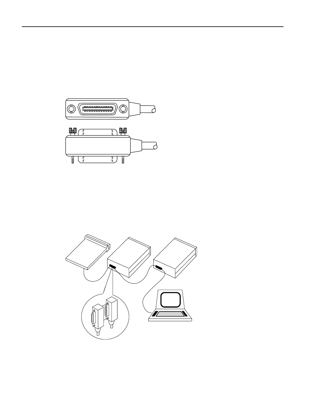
Figure 6-1
IEEE-488 connector
To allow many parallel connections to one instrument, stack the connectors. Two screws
are located on each connector to ensure that connections remain secure. Figure 6-2 shows
a typical connecting scheme for a multi-unit test system.
Figure 6-2
IEEE-488 connections
Instrument
Controller
Instrument Instrument