Models 2510 and 2510-AT User’s Manual Remote Operations 6-5
To avoid possible mechanical damage, stack no more than three connectors on any one
unit.
NOTE To minimize interference caused by electromagnetic radiation, use only shielded
IEEE-488 cables. Available shielded cables from Keithley are Models 7007-1
and 7007-2.
To connect the Model 2510 to the IEEE-488 bus, follow these steps:
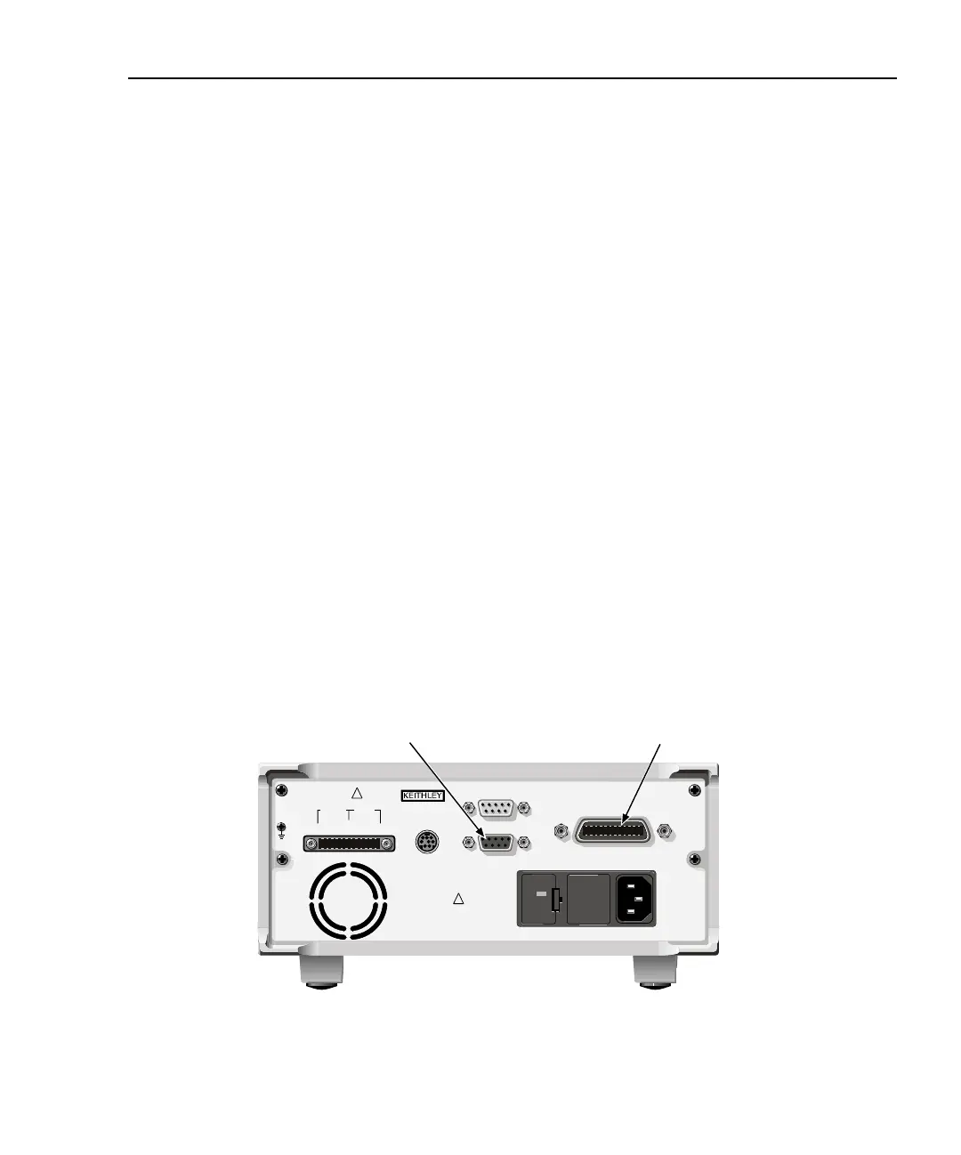
1. Line up the cable connector with the connector located on the rear panel. The con-
nector is designed so it will fit only one way. Figure 6-3 shows the location of the
IEEE-488 connector.
2. Tighten the screws securely, making sure not to overtighten them.
3. Connect any additional connectors from other instruments as required for your
application.
4. Make sure the other end of the cable is properly connected to the controller. Most
controllers are equipped with an IEEE-488 style connector, but a few may require a
different type of connecting cable. See your controller’s instruction manual for
information about properly connecting to the IEEE-488 bus.
NOTE You can only have 15 devices connected to an IEEE-488 bus, including the con-
troller. The maximum cable length is either 20 meters or two meters multiplied
by the number of devices, whichever is less. Not observing these limits may
cause erratic bus operation.
Figure 6-3
IEEE-488 and RS-232 connector locations
WARNING:NO INTERNAL OPERATOR SERVICABLE PARTS,SERVICE BY QUALIFIED PERSONNEL ONLY.
WARNING:NO INTERNAL OPERATOR SERVICABLE PARTS,SERVICE BY QUALIFIED PERSONNEL ONLY.
CAUTION:FOR CONTINUED PROTECTION AGAINST FIRE HAZARD,REPLACE FUSE WITH SAME TYPE AND RATING.
CAUTION:FOR CONTINUED PROTECTION AGAINST FIRE HAZARD,REPLACE FUSE WITH SAME TYPE AND RATING.
120
LINE RATING
100-240VAC
50, 60 HZ
90VA MAX
LINE FUSE
SLOWBLOW
2.5A, 250V
!
!
CAT I
Model 2510
RS-232
Connector
IEEE-488
Connector
IEEE-488
(ENTER IEEE ADDRESS
WITH FRONT PANEL MENU)
MADE IN
U.S.A.
ENABLE-DIG I/O
RS-232
TRIGGER
LINK
OUTPUT INPUT
F+ S+ S- F- F+ F- S+ S-
ISOLATION FROM EARTH: 30V MAX.