5-2 Digital I/O Port and Output Enable Models 2510 and 2510-AT User’s Manual
Digital I/O port
The Model 2510 has a digital input/output port that can be used to control external digital
circuitry and for a test fixture output enable circuit.
Port configuration
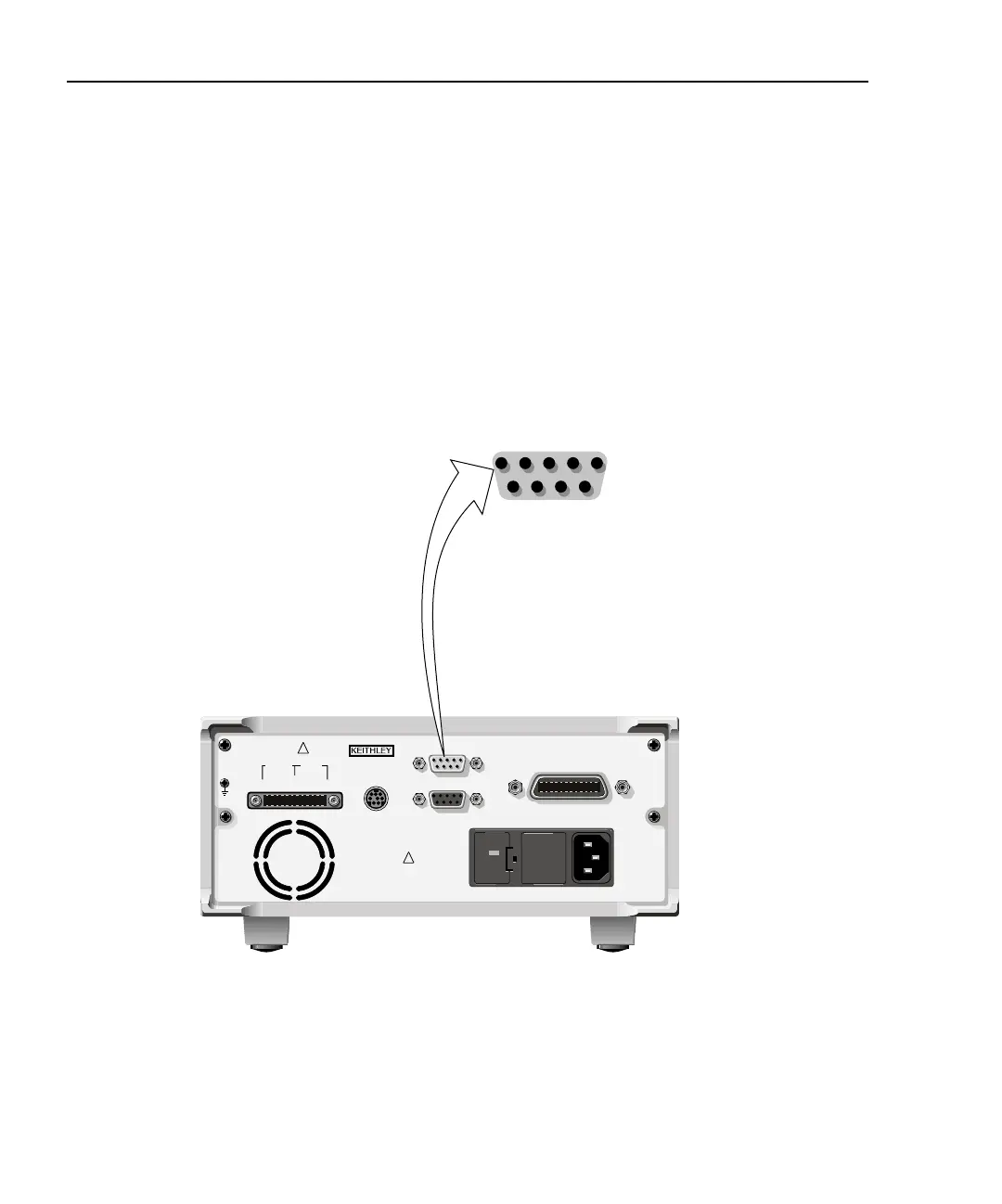
The Digital I/O Port (ENABLE - DIG I/O connector) is located on the rear panel and is
shown in Figure 5-1. Note that a standard male DB-9 connector is used.
Figure 5-1
Digital I/O port
Digital output lines
The port provides four output lines. Each open-collector output can be set high (+5V) or
low (0V). Each output line can source up to 2mA or all four lines together can sink up to
500mA.
WARNING:NO INTERNAL OPERATOR SERVICABLE PARTS,SERVICE BY QUALIFIED PERSONNEL ONLY.
WARNING:NO INTERNAL OPERATOR SERVICABLE PARTS,SERVICE BY QUALIFIED PERSONNEL ONLY.
CAUTION:FOR CONTINUED PROTECTION AGAINST FIRE HAZARD,REPLACE FUSE WITH SAME TYPE AND RATING.
CAUTION:FOR CONTINUED PROTECTION AGAINST FIRE HAZARD,REPLACE FUSE WITH SAME TYPE AND RATING.
120
LINE RATING
100-240VAC
50, 60 HZ
90VA MAX
LINE FUSE
SLOWBLOW
2.5A, 250V
!
!
CAT I
Model 2510
1 = Digital Output #1
2 = Digital Output #2
3 = Digital Output #3
4 = Digital Output #4
5 = Ground
6 = Not Used
7 = +5V
8 = Output Enable
9 = Ground
15
69
IEEE-488
(ENTER IEEE ADDRESS
WITH FRONT PANEL MENU)
MADE IN
U.S.A.
ENABLE-DIG I/O
RS-232
TRIGGER
LINK
OUTPUT INPUT
F+ S+ S- F- F+ F- S+ S-
ISOLATION FROM EARTH: 30V MAX.