Models 2510 and 2510-AT User’s Manual Basic Operation 3-17
Setpoint tolerance operation
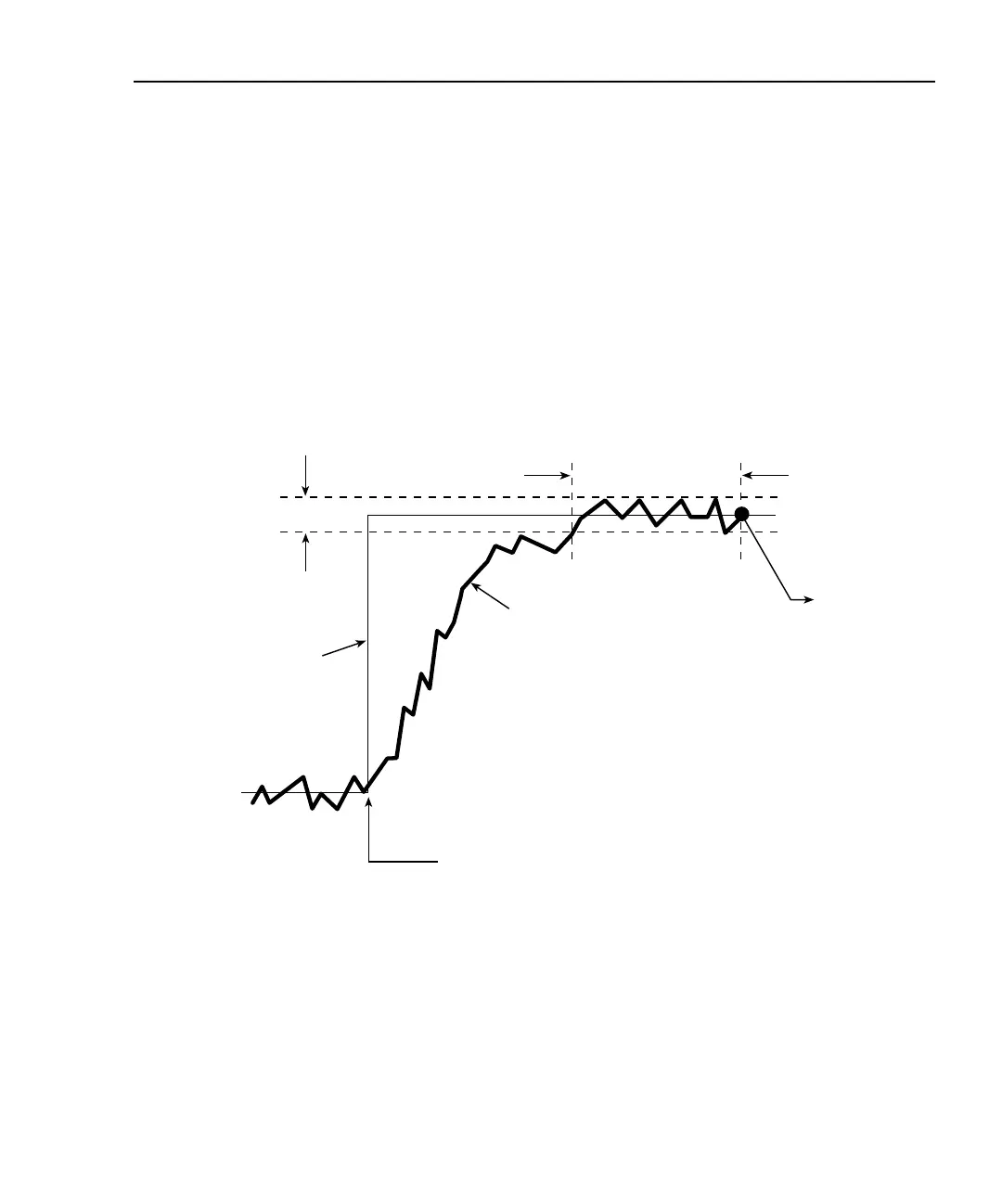
Figure 3-2 demonstrates basic setpoint tolerance operation. Operation begins at the Initial
Setpoint where the temperature stabilizes at the programmed setpoint. Once the setpoint
has been changed (either from the front panel or with a remote command), the temperature
gradually increases to the new setpoint as shown. Once the temperature reaches the Set-
point Tolerance Percentage value, it then waits until the number of readings within the Set-
point Tolerance Window have occurred, at which point the Final Setpoint is reached. At
that point, the unit issues an SRQ over the bus (if programmed to do so) and turns on the
“*” annunciator to indicate the final setpoint has been reached.
Figure 3-2
Setpoint tolerance operation
NOTE Setpoint tolerance SRQs can be used to generate a temperature sweep. See
Appendix E for details and an example program.
Setpoint Tolerance
Window
Final Setpoint
Remote Command or
Front Panel Changes
Setpoint
Setpoint Tolerance
Percentage
Setpoint Change
Initial Setpoint
SRQ Generated
When Final
Setpoint is Reached.
Not Drawn to Scale
Measured
Temperature

 Loading...


